7. Insert the cable through rubber grommet and terminate the cable end. The cabling for
installation is standard EIA/TIA 586B. For reference, the wiring diagram is included below the
programming information.
8. Insert the cable end into the CPE. The tab on the end should click when properly seated in the
radio unit. Confirm the end is securely seated in the radio unit. Slide the rubber grommet into
the cable entry point. It will fit snugly and recess into the case approximately ½ the thickness of
the grommet.
9. Complete the wire run to the entry point of the building and install the surge suppressor per the
instructions supplied with the surge device.
10. Connect the power cord with the power supply and insert it into a surge protected outlet or
uninterruptible power supply (UPS). Connect the cable leading from the surge device to the
power supply port marked ‘POE’. Connect the port labeled ‘LAN’ to a computer for
programming with a standard patch cable. CAUTION: connecting any device other than the CPE
to the POE port may cause damage.
11. When correctly installed and powered up the CPE will issue DHCP addresses in the
192.168.100.x subnet.
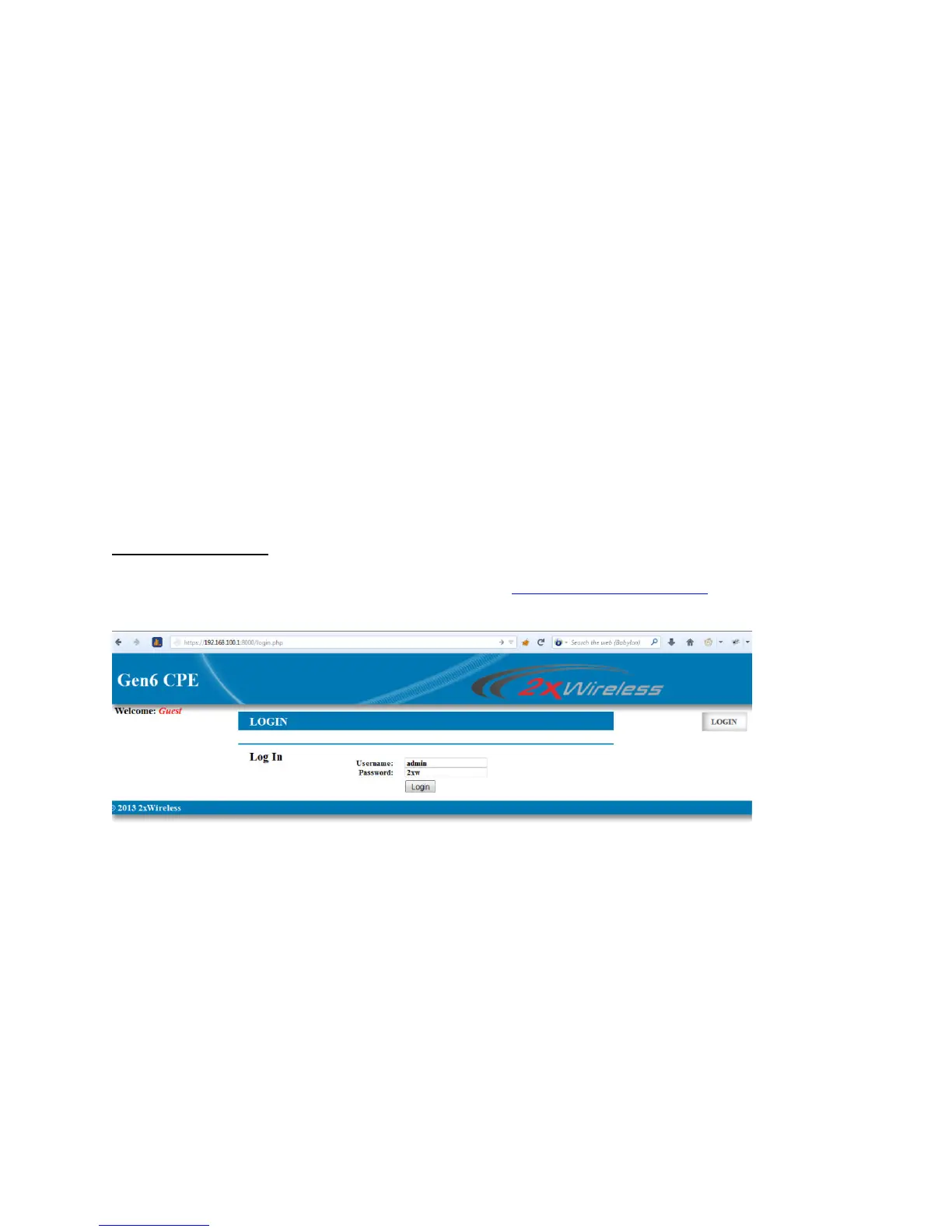
CPE Login Instructions
1. Access the web interface via the default address:
https://192.168.100.1:8000
2. At the log in prompt, enter the default username: admin and password: 2xw as shown below.
3. Choose the desired mode for the CPE to operate in. ‘Bridge’ mode will pass the network without
any routing required.
4. click the choose button.
5. You will then be able to set your network information, which his self-explanatory, including site-
surveys.
 Loading...