Image Server 2000 Owner’s Manual Page 111
Appendix A
Connector Specifications
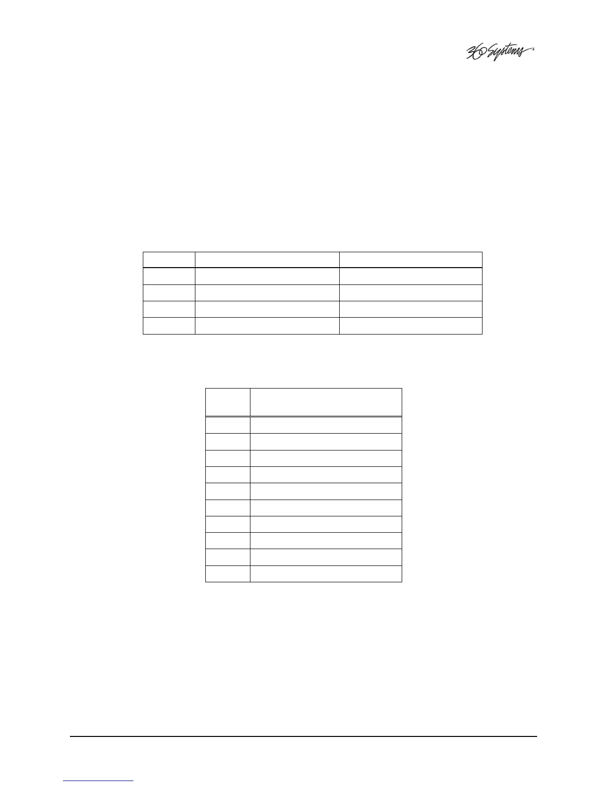
Audio XLR-3 Connector Pinout
Signals appearing on the XLR connectors are determined by the setting of the internal
Analog/Digital Audio Selection jumpers.
Pin BALANCED ANALOG AES/EBU DIGITAL
1 SHIELD
(
FRAME GROUND
)
SHIELD
(
FRAME GROUND
)
2 "
+
"
OR
HOT D
IGITAL
+
3 "
–
"
OR
COMMON D
IGITAL
-
S
HELL
F
RAME GROUND
F
RAME GROUND
Serial Control Connector Pinout
Pin
EIA-422, DB9-F
Connector
1 GND
2 Transmit A (TX–)
3 Receive B (RX+)
4 GND
5 N/C
6 GND
7 Transmit B (TX+)
8 Receive A (RX-)
9 GND
Shell
Frame ground