16 CHAPTER 1: INTRODUCING THE ACCESS POINT
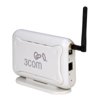
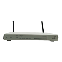
Rear Panel The rear panel (Figure 3) of the Access Point contains one LAN port, a
reset button, a power adapter OK LED and a power adapter socket.
Figure 3 Access Point - Rear Panel
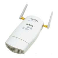
5 Wireless Antennae
The antennae on the product should be placed in a ‘V’ position when
initially installed.
CAUTION: Do not force the antennae round further than 90 degrees in
either direction.
6 Power Adapter Socket
Only use the power adapter supplied with this Access Point. Do not use
any other adapter.
7 Power Adapter OK LED
Green
Indicates that the power adapter is supplying Power to the Access Point.
If the LED is off, there may be a problem with the power adapter or
adapter cable.
8 Ethernet Port
Use the supplied patch cable to connect the Access Point to the LAN. The
port will automatically adjust to the correct speed and duplex.
9 Reset Button
This button allows you to reset the unit to factory defaults.
8 9
Ethernet
5 5
RESET
6 7
OK
 Loading...