12
Remove any large volumes of oil/water from supplied air line prior to connecting the system.
Purge air through the system for a minimum of five (5) minutes on initial start-up.
NOTE: If excessive oil/water is present, install a separate coalescing prefilter prior to the
system inlet. (Fig. 4)
Install the industrial interchange plug into the threaded inlet to the panel. Install all eight (8)
industrial interchange quick disconnects into the eight (8) threaded outlets from the panel.
Connect the inlet air supply and outlet compressed air hoses.
Pressurize the system and set the regulator to the appropriate pressure required by the respirator air
control device.
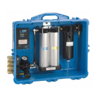
Adjust air sample metering valve’s adjustment knob (Fig. 5) so the black floating ball is within the
green boxed area etched on valve body. Proper air sample is now being metered to the CO
monitor. Periodically check to be sure ball is floating freely in this area by turning adjustment
knob and noting movement of ball.
Fig. 5
W WARNING
To meet NIOSH requirement 42 CFR 84, subpart 84.150 for minimum and maximum airflow
(4-15 cfm, 113-425 lpm), the air control valves approved for use with the 3M respirators must
be operated within the supply pressure ranges and hose lengths stated in their User Instructions.
Failure to do so may adversely affect respirator performance and result in sickness
or death.
 Loading...