English / 34-8720-2487-1 9
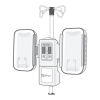
3. Cart Installation: Place the unit in the center of the cart with the warming unit
feet aligned with the recesses in thecart.
(Note: The front rolling cart casters arelockable.)
System
MODEL
675
CartInstallation
4. Push down to snap the warming unit inplace.
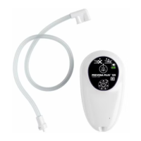
Attaching thehose
ServiceFrequency
Asneeded
Tools/Equipment
• Hose
Method
1. Align the triangle on top of the warming unit hose
connection with the notched groove on the hoseend.
2. Push the hose in and turn clockwise approximately ¼ turn
until it snaps intoplace.
Removing theHose
ServiceFrequency
Asneeded
Tools/Equipment
• None
Method
1. Hold the warming unit end of the hose and rotate
counter-clockwise approximately ¼ turn until
itstops.
2. Pull the hose straight out of the warmingunit.
Testing theAlarm
ServiceFrequency
Asneeded
Tools/Equipment
• None
Method
1. Connect the warming unit to a grounded powersource.
2. Verify the alarm sounds for approximately one beep and thensilences.
Replacing the AirFilter
ServiceFrequency
Every 12months or 500hours ofuse.
The Change Filter indicator will display on the LCD screen after 500hours
ofuse.
Tools/Equipment
• Replacement air filter (Use only 3Msupplied airfilter)
• #2Phillipsscrewdriver
CAUTION: Do not attempt to clean the air filter as it may be contaminated from
use. Discard the filter in a manner consistent with institutionalprotocol.
Method
1. Disconnect the warming unit from the
grounded powersource.
2. If the warming unit is mounted to a rolling
cart remove the cart by gently pulling on
the front tab on the cart and lifting the
warming unit off thecart.
3. Turn the warming unit upsidedown.
4. Remove the 2screws located in the
bottom of the warmingunit.
5. Lift the filter cover off the warmingunit.
6. Remove the air filter and discardit.
7. Place the new filter in the filter
compartment in eitherorientation.
8. Replace the filter cover on the
warmingunit.
9. Replace the 2screws in the filtercover.
10. If the warming unit was attached to a
rolling cart, place the warming unit in the
center of the cart and push down to snap
it inplace.
11. Connect the warming unit to a properly
grounded powersource.
12. Access the Diagnostic mode (see Diagnostic Modesection).
13. Navigate to the FILTER TIMER menu option and select it by pressing the
Ambientbutton.
14. Reset the filter timer by highlighting Yes and pressing the Ambientbutton.
15. Verify the filter time displayed at the top of the LCD screen displays0.0.
16. Exit the Diagnostic Menu by pressing the Powerbutton.
Calibrating the OperatingTemperature
CAUTION
Perform all temperature testing of the warming unit with a 3MModel
22110Temperature TestUnit.
3Massumes no responsibility for the reliability, safety, or performance of the
temperature management system if temperature tests or adjustments are made
in any manner other than those described here. Improper measurement or
adjustment of the warming unit’s normal operating temperature could result in
patient exposure to temperatures outside of the indicated range and may lead to
patientinjury.
ServiceFrequency
Every 12months or 500hours ofuse.
Tools/Equipment
• Model 22110Temperature TestUnit
• Calibrated thermocouplemonitor
Notes:
• The Model 22110temperature test unit simulates the operating characteristic of
3Mblankets and gowns when used with the warmingunit.
• When using the Model 22110temperature test unit, take temperature readings
using a calibrated thermocouple monitor that can accept a male, subminiature
connector and read a “K” style thermocouple (e.g., a Fluke 52 K/J Thermometer).
If the test unit’s connector does not fit your thermocouple monitor, remove the
connector from the test unit and attach a connector that fits your monitor. Be
certain to observepolarity.
Method
1. Connect the warming unit to a grounded power source. The unit performs a
self-test and automatically proceeds to Standbymode.
2. Connect the temperature test unit to the end of the warming unit hose by fully
inserting the hose end up to the hose card stopflange.
3. Access the Diagnostic mode (see Diagnostic Modesection).
4. Navigate to the CALIBRATION menu option then press the Ambient button.
The warming unit is now in Calibration mode. In this mode, the warming unit
performs the followingtasks:
• Blower turnsON.
• Heater elements turnON.
• The LCDdisplays:
a. The text “DISPLAY” followed by the calibrated temperature of the air
exiting the warmingunit.
b. The text “OFFSET” followed by the offset value. The offset value is the air
temperature difference between the warming unit hose connection (i.e.
air entering the hose) and the hose end (i.e. air exiting thehose).
5. Wait for the temperature shown on the warming unit’s LCD display to stabilize
at 43.0°C ± 0.1°C (about 3-5minutes).
6. Compare the temperature shown on the LCD display and the temperature of
the thermocouple (test kit)monitor.
• If the temperatures match, press the Ambient button to save and return
to the Diagnostic Mode mainscreen.
System
MODEL
675
Filter
Screws
Filter Cover

 Loading...