English / 34-8720-2487-1 5
Proper Use andMaintenance
3Massumes no responsibility for the reliability, performance, or safety of the warming
unit if the following eventsoccur:
• Modifications or repairs are not performed by a qualified, medical equipment
service technician who is familiar with good practice for medical devicerepair.
• The unit is used in a manner other than that described in the Operator’s or
ServiceManuals.
• The unit is installed in an environment that does not meet the appropriate
electrical and groundingrequirements.
• The warming unit is not maintained in accordance with the procedures
described in the ServiceManual.
Read Before ServicingEquipment
All repair, calibration and servicing of the warming unit require the skill of a qualified,
medical equipment service technician who is familiar with good practice for medical
device repair. No further 3Mwarming unit-specific special training, licensing or
certification is required for servicing of Model675warming unit. If service does not
require the manufacturer’s attention, the Model675Service Manual provides the
technical information needed to service the unit. Perform all repairs and maintenance
in accordance with the instructions in the Model675Service Manual. For additional
service information please contact 3MTechnicalSupport.
SafetyInspection
Perform a safety inspection after making repairs to the BairHugger
Model675warming unit and before returning the unit to service. A safety inspection
should include calibrating the operating temperature settings and testing the
over-temperature detection function as described in this service manual as well as
testing for leakage current and continuity check on safetyground.
Overview
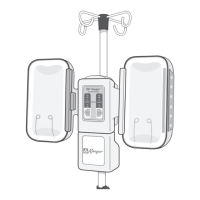
Overview of Model675WarmingUnit
The figure below illustrates the location of the warming unitfeatures.
Control
Panel
Carrying
Handle
IV Pole
Clamp
Warming Unit
Hose
SystemSystem
MODEL
675
Power
Cord
Warming Unit
Hose
Front
Equipotential
Stud
Back
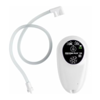
Overview of ControlPanel
The front control panel button locations and indicators are described and illustrated in the figurebelow.
Display Screen (LCD):
• Shows temperature of air coming out of
thehose
Temperature Settings:
•
(Ambient)
• 32° C (89.6° F)
• 38° C (100.4° F)
• 43° C (109.4° F)
Green LED:
• Shows selected temperature setting
Power:
• Green = On
• Amber = Standby

 Loading...