Installation
3M™ Drive-Thru Systems Model G5 and Model XT-1
Installation Manual
March 2014 – Revision 2.0
Page 29 of 74
Simple Circuit Example
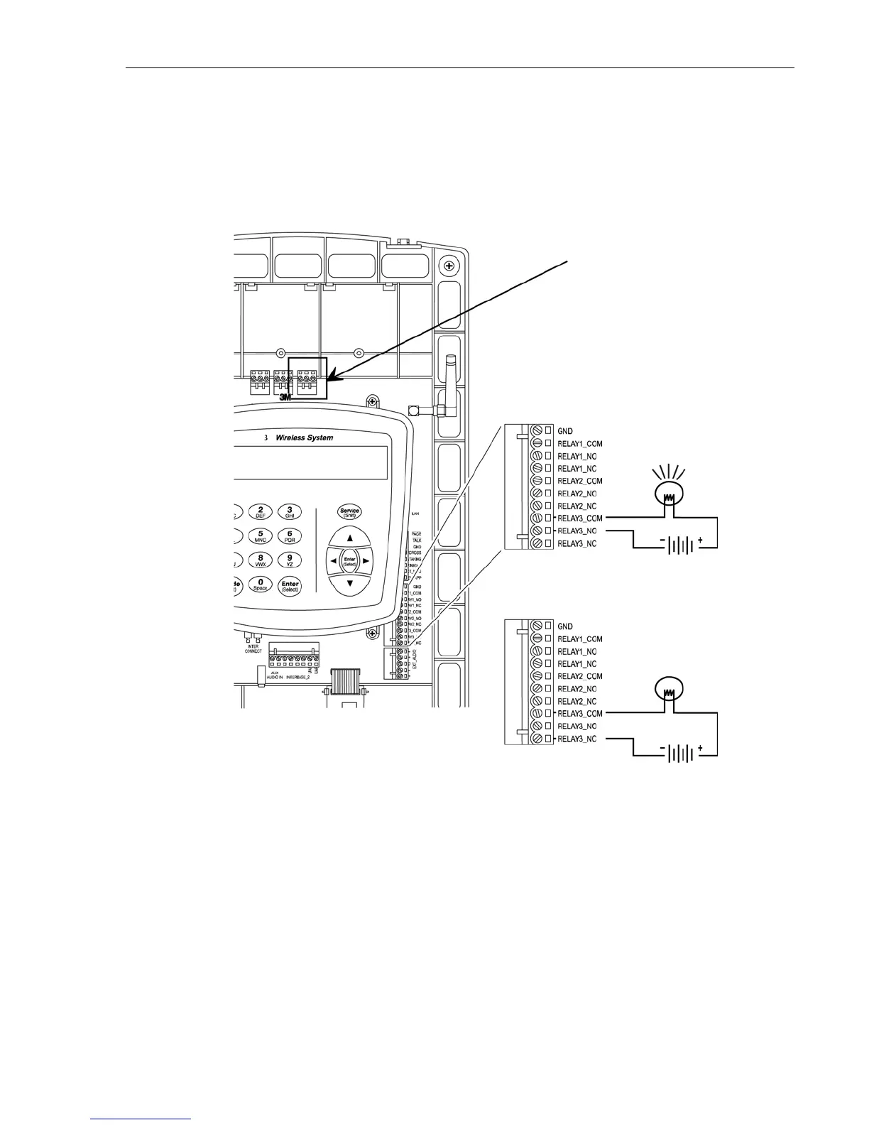
Figure 12 shows a simple DC circuit (a light and DC power supply) being
operated by auxiliary relay 3. To make the light turn on when a vehicle is
detected, terminals RELAY3_COM and RELAY3_NO (normally open) would
be used. To make the light turn off when a vehicle is detected, terminals
RELAY3_COM and RELAY3_NC (normally closed) would be used.
Figure 12
Vehicle Approach Monitor
If one of your vehicle detectors will be used as a vehicle approach monitor, use
an auxiliary as shown in Figure 13.
Controls RELAY3
If RELAY3_NO terminal is used,
vehicle detection closes the relay (to
complete this circuit and turn on this
light).
If RELAY3_NC terminal is used,
vehicle detection opens the relay
(to interrupt this circuit and turn
off this light).

 Loading...