3 4
EN
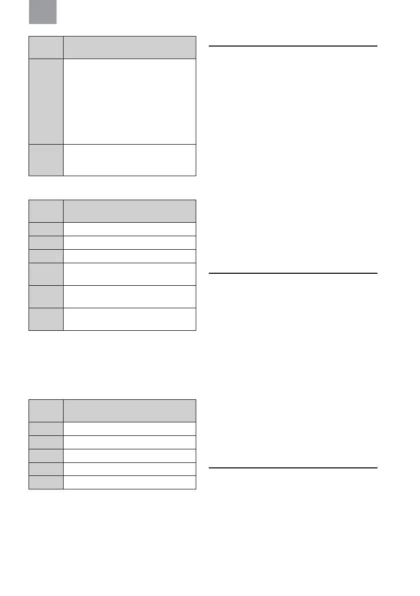
Table
ref.
Description
G:5 H = Hearing protection estimation for high
frequency sounds (ƒ ≥ 2000Hz).
M = Hearing protection estimation for medium
frequency sounds (500Hz < ƒ < 2000Hz).
L = Hearing protection estimation for low
frequency sounds (ƒ ≤ 500Hz).
SNR = Single Number Rating of hearing
protector performance
G:6 S = Small
M = Medium
L = Large
EN 352-6 Electrical safety related audio input
Wireless input for two-way radio
Table
ref.
Description
H:A External wireless safety related audio input
H:1 Input signal level U (mV
RMS
)
H:2 Sound output level (dB(A))
H:3 Criterion input signal (mV
RMS
) for which the
sound output level is equal to 82 dB(A)
H:4 SPL. Sound output level for maximum input
signal (dB(A))
H:5 Time equivalent to 82 dB(A) over 8h (hh:mm)
for maximum input signal
4.3. CARRIER DEVICES
These earmuffs should be tted to and used only with the
carrier devices listed in table H. These earmuffs were tested
in combination with the carrier devices listed in table H, and
may give different levels of protection if tted to different
carrier devices.
Explanation of the carrier attachment table:
Table
ref.
Description
J:A Compatible carrier devices
J:1 Manufacturer
J:2 Model
J:3 Attachment code
J:4 Head size: S = small, M = medium, L = large
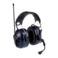
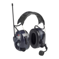
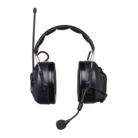
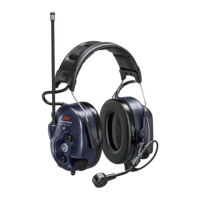
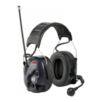
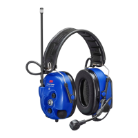
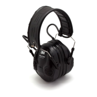
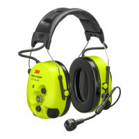
5. OVERVIEW
(Figure A:A - A:C)
A:A Headband versions
A:B Neckband versions
A:C Carrier attachment versions
5.1. A) COMPONENTS
(Figure A)
(A:1) Headband (PVC)
(A:2) Headband padding (PVC foil)
(A:3) Headband wire (stainless steel)
(A:4) Two-point fastener (POM)
(A:5) Ear cushion (PVC foil and PUR foam)
(A:6) Attenuation cushion (PUR foam)
(A:7) Cup (ABS)
(A:8) Speech microphone (electret microphone) (ABS, PA)
(A:9) On/Off/Mode button (PBT)
(A:10) (+) button (PBT)
(A:11) (–) button (PBS)
(A:12) Antenna (PE, ABS, TPE)
(A:13) Speech microphone input (J22) (ABS)
(A:14) PTT button (PBT)
(A:15) Battery lid (PP/stainless steel)
(A:16) Carrier attachment (POM, PA66)
(A:17) Neckband cover (PO)
6. SETUP
6.1. GENERAL
The following points covers the main actions to make the
product ready for operation.
6.2. REMOVE/INSTALL BATTERIES
(Figure F)
Make sure you have read and understood the contents of
Chapter 2. Safety before replacing the battery/batteries.
F:1. Loosen the screw holding the battery lid using a screw
driver. Turn the screw counter clockwise.
F:2. Tilt the lid top outwards (1). Pull the lid downwards (2) in
order to remove it from the headset.
F:3. Insert or replace the batteries. Make sure the polarity
corresponds to the markings. Install the lid on the headset
and tighten the screw.
Low battery level is indicated by a voice message: “battery
low”, repeated every ve minutes. If the batteries are not
replaced, a “battery empty” warning will eventually be heard.
The unit will then switch off automatically.
NOTE: Performance may deteriorate as the batteries get low.
7. FITTING INSTRUCTIONS
7.1. GENERAL
Inspect the hearing protector before each use. If damaged,
select an undamaged hearing protector or avoid the noisy
environment.
NOTE: Brush aside hair around your ears so the ear cushions
(A:5) t snugly.
Spectacle frames should be as thin as possible and t close
to the head to minimise acoustic leakage.