6
Install and remove HE lter, lter/cartridge, prelter, spark arrestor and cover
Install and remove the lter/cartridge in non-hazardous locations only.
1. Inspect the lter/cartridge to be installed:
• Filter/cartridge is intact with no tears, cracks, distortion or other damage.
• The inner circular gasket is present and intact with no tears, cuts or distortions. Wipe the lter seal with a clean cloth
if necessary. Dispose of and replace lter/cartridge if damage is noted or suspected. NOTE: The 3M™ Versao™
Powered Air Purifying Respirator TR-600/TR-800 Filter/Cartridge Assemblies have both an inner circular gasket
(Fig.3-6) and outer rectangular barrier (Fig. 3-5). The inner gasket is the primary seal between the lter and blower.
The outer barrier acts to keep dirt and debris from behind the lter.
2. To install the lter/cartridge:
• Conrm the TR-800 is powered off. Do not install or replace lter/cartridges while the motor/blower is running.
Option 1: Using the lter/cartridge with prelter/spark arrestor and lter cover.
Fig. 4 (Recommended for most applications).
NOTE: Use the specied lter cover for the lter/cartridge. See “Specications” section for correct pairing.
• Hold the lter cover so it faces down (Fig. 4-1).
• (If required) insert the metal mesh spark arrestor/prelter into the cover, ensuring the cutouts are aligned properly
(Fig.4-2).
• (If required) insert the foam prelter, ensuring the cutouts are aligned properly (Fig. 4-3).
• Insert the lter/cartridge into the lter cover ensuring the bottom latching tab snaps into place (Fig. 4-4). The
lter/cartridge label must be visible in the cover window (Fig. 13).
• Place the hinge side of the lter/cartridge into the motor/blower (Fig. 5-1) and snap latch side into the lter latch
(Fig.5-2).
• Gently tug on lter/cartridge to ensure proper attachment at both sides.
Option 2: Using the lter/cartridge without the lter cover.
(May typically be used in applications when lter/cartridges are changed very frequently to reduce potential for
cross-contamination.)
NOTE: Using the lter/cartridge without the lter cover leaves it more susceptible to damage from external forces and
liquid spray.
• Place the hinge side of the lter/cartridge into the motor/blower hinge (Fig. 5-1) and snap latch side into the lter
latch (Fig. 5-2).
• Gently tug on lter/cartridge to ensure proper attachment at both sides.
1
2
6
3
5
4
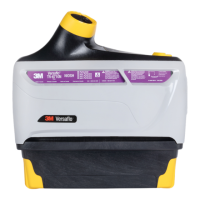
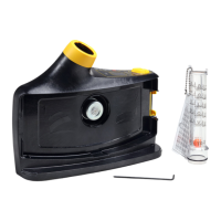
1. Filter cover
2. Spark arrestor/prelter
3. Prelter
4. Filter/cartridge
5. Outer barrier
6. Inner gasket
Fig. 3

 Loading...