100-02643-A-DEV02
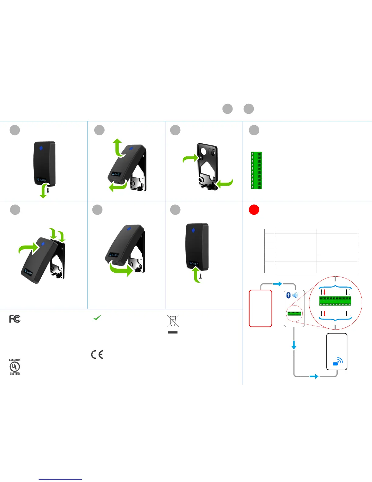
1-0VSupply voltage ground
2-+VdcSupply voltage (+10Vdc to +16Vdc)
3-DATA1/CLKWiegand or Clock/Data output
4-DATA0/DATWiegand or Clock/Data output
5-GREENGreen LED control input
6-REDRed LED control input
7-BuzzerBuzzer control input
8-TMPR/CPTamper or Card Present output
9-RS485-RS485 Bus
10-RS485+RS485 Bus
If fitted, remove reader module
securing screw.
Pull bottom edge of reader module
away from the backplate, and lift up.
Mount the reader backplate to a flat
surface using suitable hardware having a
diameter no greater than 0.15 in (4mm).
Once the backplate has been mounted, make wire connections to
the reader module in accordance with the screw terminal
connections shown below, and your control panel requirements.
Ensure the cable does not impair or prevent the reader module
being secured.
Position the reader module, ensuring
the top-edge fixing lugs engage
correctly with the recesses located at
the top of the backplate.
Swing the bottom edge of the module
down and forward until you feel the unit
click shut.
Secure the reader module to the
backplate using the M3x100mm screw
as supplied.
1423
567
If required, you may opt to
use security screw.
4b
Applicable to 3M Inline add-on reader only. The following is a
diagrammatic representation of the wiring configuration providing a
Bluetooth capabaility to most existing installations. Please consult
your installer and the manufacturer’s details of your existing control
panel and access control reader.
( THIS CONFIGURATION NOT EVALUATED BY UL )
line INline OUTpin
10V
2+Vdc (+12Vdc)
3N/A
4N/A
5N/A
6N/A
7N/A
8N/A
9RS485 -
10RS485 +
line IN
line OUT
0V
+Vdc (+12Vdc)
N/A
N/A
N/A
N/A
N/A
N/A
RS485 -
RS485 +
existing
ACCESS
CONTROL
READER
line out from 3M Inline reader
security
access
CONTROL
PANEL
3M Inline reader
line in from control panel
1
2
3
4
5
6
7
8
9
10
compliant
RoHS
These devices comply with Part 15 of the FCC Rules.
Operation is subject to the following two conditions:
(1) this device may not cause harmful interference,
and (2) this device must accept any interference
received, including interference that may cause
undesired operation.
Any changes or modifications not expressly approved by
the party responsible for compliance could void the
user’s authority to operate the equipment.
These devices contains: FCC ID: TCZ-10103751G1
EQUIPMENT
BP21018
2AKUW-AV00
2AKUW-AV90
These RFID proximity readers comply with
the essential requirements and relevant
provisions of:
EU Directive 2014/53/EC
Together with information provided by
suppliers and subcontractors, these devices
comply with the requirements and relevant
provisions of:
EU Directive 2011/65/EC.
This symbol on the product or on its packaging
indicates that the product must not be disposed of
with normal household waste. Instead, it is your
responsibility to dispose of your waste equipment
by arranging to return it to a designated collection
point for the recycling of waste electrical and
electronic equipment. By separating and recycling
your waste equipment at the time of disposal you
will help to conserve natural resources and ensure
that the equipment is recycled in a manner that
protects human health and the environment.
EU Directive 2012/19/EU
These notes are provided as a general guidance for mounting, fixing and connecting 3millID - 3M series RFID
readers. Please consult your installer and the manufacturer’s details of your control panel, when configuring
your access security system.
GENERAL GUIDANCE NOTES to APPLIES TO ALL READER MODELS LISTED OVERLEAF
17
 Loading...