5
DIMENSIONS AND CAPACITIES DATA
TABLE 2 - RECOVERY CAPACITIES
Element
Wattage
(Upper/Lower)
INPUT
KW
U.S. Gallons/Hr and Litres/Hr at TEMPERATURE RISE INDICATED
F° 36F° 40F° 54F° 60F° 72F° 80F° 90F° 100F° 108F° 120F° 126F°
C° 20C° 22.2C° 30C° 33.3C° 40C° 44.4C° 50C° 55.5C° 60C° 66.6C° 70C°
NON-SIMULTANEOUS
/1500 GPH 17 15 11 10 8 8 7 6 6 5 5
1.5 LPH 64 58 43 38 32 29 26 23 21 19 18
/2000 GPH 23 20 15 14 11 10 9 8 8 7 6
2.0 LPH 85 77 57 51 43 38 34 31 28 26 24
/2500 GPH 28 25 19 17 14 13 11 10 9 8 8
2.5 LPH 107 96 71 64 53 48 43 38 36 32 30
3000/3000 GPH 34 30 23 20 17 15 14 12 11 10 10
3.0 LPH 128 115 85 77 64 58 51 46 43 38 37
4000/4000 GPH 45 41 30 27 23 20 18 16 15 14 13
4.0 LPH 170 153 114 102 85 77 68 61 57 51 49
4500/4500 GPH 51 46 34 30 25 23 20 18 17 15 14
4.5 LPH 192 173 128 115 96 86 77 69 64 58 55
5000/5000 GPH 56 51 38 34 28 25 23 20 19 17 16
5.0 LPH 213 192 142 128 107 96 85 77 71 64 61
6000/6000 GPH 68 61 45 41 34 30 27 24 23 20 19
6.0 LPH 256 230 170 153 128 115 102 92 85 77 73
SIMULTANEOUS OPERATION
3000/3000 GPH 68 61 45 41 34 30 27 24 23 20 19
6 LPH 256 230 170 153 128 115 102 92 85 77 73
4000/4000 GPH 90 81 60 54 45 41 36 32 30 27 26
8 LPH 341 307 227 205 170 153 136 123 114 102 97
4500/4500 GPH 101 91 68 61 51 46 41 36 34 30 29
9 LPH 384 345 256 230 192 173 153 138 128 115 110
5000/5000 GPH 113 101 75 68 56 51 45 41 38 34 32
10 LPH 426 384 284 256 213 192 170 153 142 128 122
6000/6000 GPH 135 122 90 81 68 61 54 49 45 41 39
12 LPH 511 460 341 307 256 230 205 184 170 153 146
Recovery capacities at 100° F rise equal: for non-simultaneous element operation = 4.1 gal. x KW of one element; for simultaneous element operation = 4.1 gal. x 2/3 KW of
both elements. For other rises multiply element KW as previously explained by 410 and divide by temperature rise. Full load current for single phase = total watts : voltage.
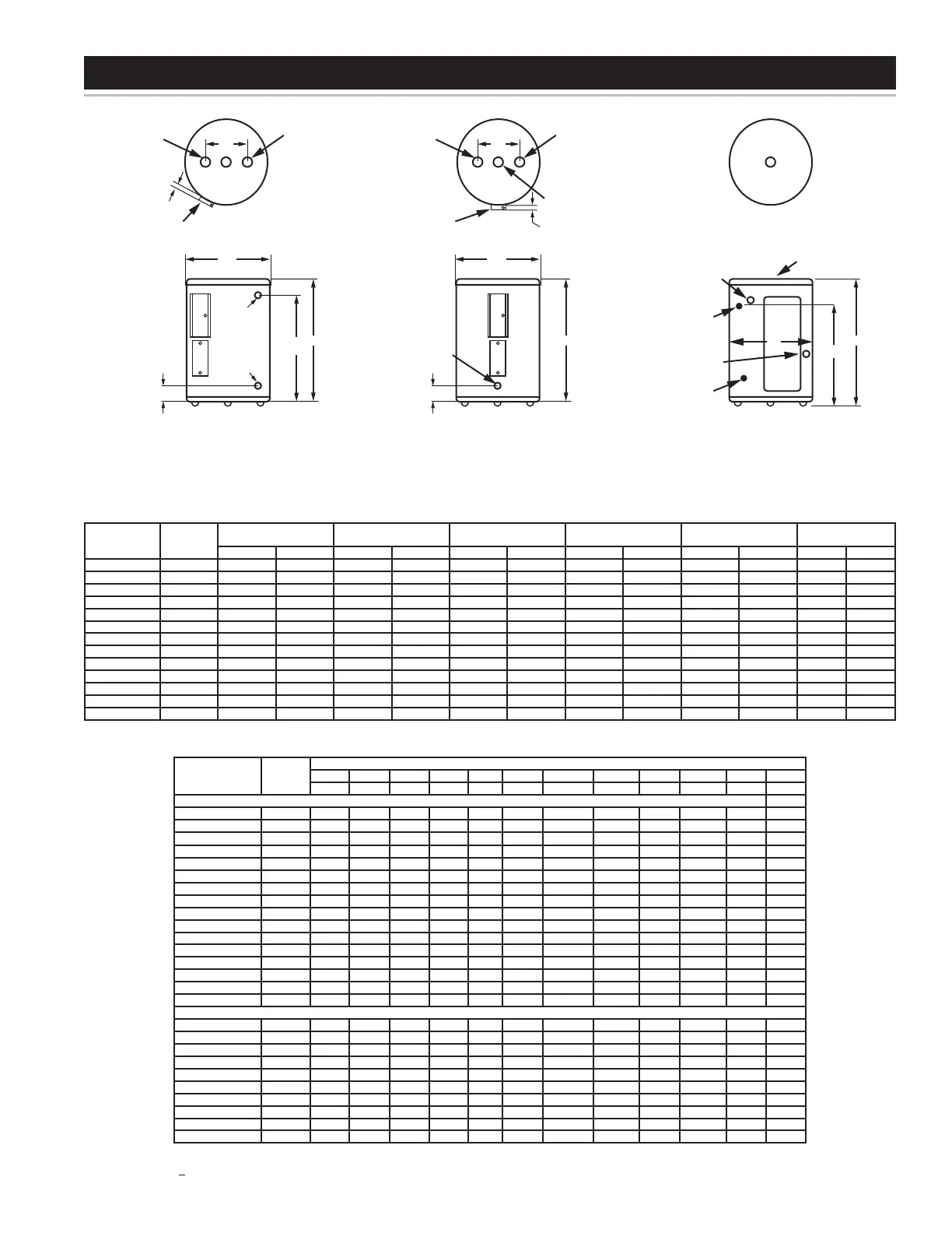
TABLE 1 - ROUGH-IN DIMENSIONS
Models
Dimensions
No. of
Elements
Tank Capacity A B C D
Approx.
Shipping Weight
US Gals. Litres inches mm inches mm inches mm inches mm Lbs. Kg.
DEL-6 1 6 23 15 1/2 394 14 1/4 362 11 279 - - 35 15.9
DEL-10 1 10 38 18 1/4 464 18 457 12 1/2 318 - - 54 24.5
DEL-15 1 13 49 26 660 18 457 20 1/2 521 - - 58 26.3
DEL-20 1 19 74 22 1/4 565 21 3/4 552 15 3/8 391 - - 73 33.1
DEL-30 2 29 111 30 7/8 784 21 3/4 552 24 1/8 613 8 203 100 45.4
DEL-40 2 38 145 32 1/4 819 24 610 25 9/16 649 8 203 125 56.7
DEL-50 2 46 175 32 1/4 819 26 1/2 673 25 1/8 638 8 203 166 75.3
DEN-30 2 28 107 34 1/2 876 20 1/2 521 - - 8 203 98 44.5
DEN-40 2 37 143 45 1/8 1146 20 1/2 521 - - 8 203 113 51.3
DEN-52 2 46 175 54 7/8 1394 20 1/2 521 - - 8 203 131 59.4
DEN-66 2 62 237 60 3/4 1543 21 3/4 552 - - 8 203 176 79.8
DEN-80 2 75 284 59 3/8 1508 24 610 - - 8 203 211 95.7
DEN-120 2 113 428 62 7/16 1586 29 3/8 746 - - 8 203 326 147.9
FIGURE 1
3/4” (FEMALE)
NPT
NPT
2 1/2”
(63.5 mm)
JUNCTION
BOX
“D”
TOP VIEW
DEL 30/40/50
3 3/4” (95.25 mm)
FRONT VIEW
DEL 30/40/50
3 3/4” NPT
RELIEF VALVE
OPENING
BRASS
DRAIN
VALVE
“B”
“C”
“A”
TOP VIEW
DEL 6/10/15/20
FRONT VIEW
DEN 30-120
3 3/4” (95.25 mm)
DRAIN
VALVE
“B”
“A”
2 1/2”
(63.5 mm)
3/4” (FEMALE)
NPT
3/4” NPT
RELIEF VALVE
OPENING
3/4” (FEMALE)
NPT
JUNCTION
BOX
“D”
TOP VIEW
DEN 30 - 120
INLET
3/4” (FEMALE)
NPT
OUTLET
3/4” (FEMALE)
NPT
FRONT VIEW
DEL 6/10/15/20
*(NO SIDE OUTLET AVAILABLE FOR DEL-6 MODELS)
3/4” NPT
RELIEF VALVE
OPENING
ALTERNATE OUTLET
3/4” (FEMALE) NPT
ELECTRICAL
CONNECTION
“C”
“A”
“B”
 Loading...