6
L.L.
L.L.
L.
REWINDING REWINDING
REWINDING REWINDING
REWINDING
TT
TT
T
ORSION ASSEMBLORSION ASSEMBL
ORSION ASSEMBLORSION ASSEMBL
ORSION ASSEMBL
Y SPRINGY SPRING
Y SPRINGY SPRING
Y SPRING
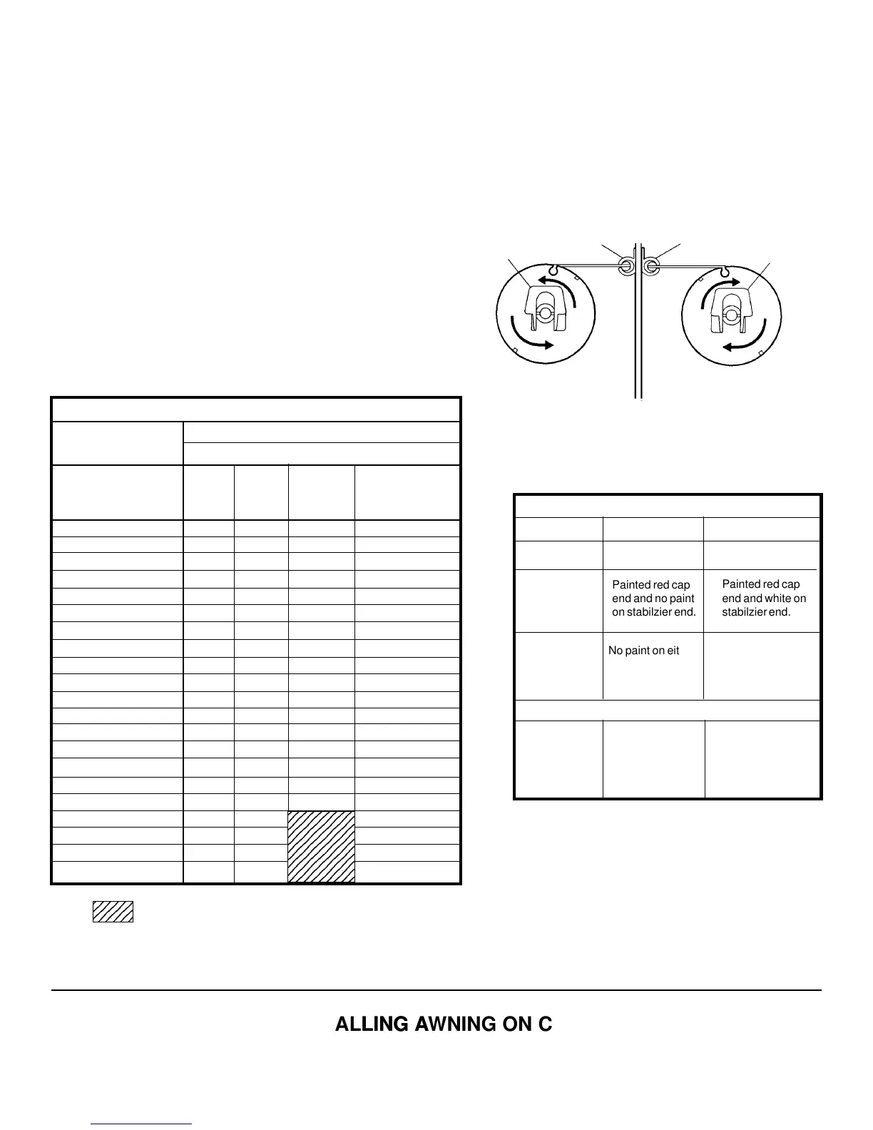
2. Rewind the torsion assembly to the number of turns
indicated by the torsion assembly Torque Chart and in
the direction shown in FIGS. 14 &15.
NOTENOTE
NOTENOTE
NOTE: If the awning is installed on a coach, complete the
following steps on a step ladder with the awning fabric
unrolled two feet from the awning rail.
1. Clamp a Vise Grip® tightly on the thickest side of the
top casting. See FIG. 4.
WW
WW
W
ARNINGARNING
ARNINGARNING
ARNING
Severe injury can result from the rapid spin-off of theSevere injury can result from the rapid spin-off of the
Severe injury can result from the rapid spin-off of theSevere injury can result from the rapid spin-off of the
Severe injury can result from the rapid spin-off of the
top casting. Use Vise Gripstop casting. Use Vise Grips
top casting. Use Vise Gripstop casting. Use Vise Grips
top casting. Use Vise Grips®
- NEVER use bare hands - NEVER use bare hands
- NEVER use bare hands - NEVER use bare hands
- NEVER use bare hands
- to handle a top casting under spring tension.- to handle a top casting under spring tension.
- to handle a top casting under spring tension.- to handle a top casting under spring tension.
- to handle a top casting under spring tension.
3. Place a 1/8" cotter pin through the hole in the end cap
and torsion rod. This will prevent the rapid spin-off of
the top casting during installation of the awning. See
FIGS. 2, 3 & 3A.
NOTENOTE
NOTENOTE
NOTE: If awning is installed on the coach, place the top
casting in the support arm and secure with the 1/4-20 hex
head bolt.
AWNING RAIL AWNING RAIL
WIND TOP
CASTING
WIND TOP
CASTING
FIG. 14
FIG. 15
RIGHT-HAND SIDE
(VIEW FROM FRONT)
LEFT-HAND SIDE
(VIEW FROM REAR)
Number of Turns
MODEL NUMBER
5000 7000 7500 9500
Awning Length (Ft.) 8000 Grande Pavillion
8500
9000
86-8-
96-8-
10 6 8 8 -
10' 8" 6 8 8 -
11 6 8 8 -
12 6 8 8 -
13 7 9 9 -
14 7 9 9 -
15 8 10 10 -
16 8 10 10 6
16'6" - - 12 -
17 10 12 12 6
18 10 12 12 7
19 11 13 13 7
19'6" - - 13 -
20 11 13 13 -
21 11 13 13 8
22 12 - 14 8
23 12 - 14 8
24 12 - 14 9
25 12 - 14 9
TORSION ASSEMBLY TORQUE SPECIFICATIONS
23456789
23456789
23456789
23456789
23456789
23456789
23456789
23456789
23456789
Painted red cap
end and no paint
on stabilzier end.
Painted red cap
end and white on
stabilzier end.
No paint on either
end.
Painted white on
cap end and no
paint on stabilizer
end.
Length
22' 14 8
23' 14 8
24' 14 8
25' 14 8
Wire Dia.Wire Dia.
Wire Dia.Wire Dia.
Wire Dia. .120 .140
RHRH
RHRH
RH
LHLH
LHLH
LH
StandardStandard
StandardStandard
Standard
Heavy DutyHeavy Duty
Heavy DutyHeavy Duty
Heavy Duty
SPRING IDENTIFICATION CHART
TURNS OF TENSIONTURNS OF TENSION
TURNS OF TENSIONTURNS OF TENSION
TURNS OF TENSION
2345
2345
See Spring Indentification Chart for No. of Turns
M.M.
M.M.
M.
INST INST
INST INST
INST
ALLING AALLING A
ALLING AALLING A
ALLING A
WNING ON COWNING ON CO
WNING ON COWNING ON CO
WNING ON CO
AA
AA
A
CHCH
CHCH
CH
1. Follow installation instructions for the awning when replacing on coach.
 Loading...