Ascotel IntelliGate 2025/2045/2065
Part 4 Installing terminals 829
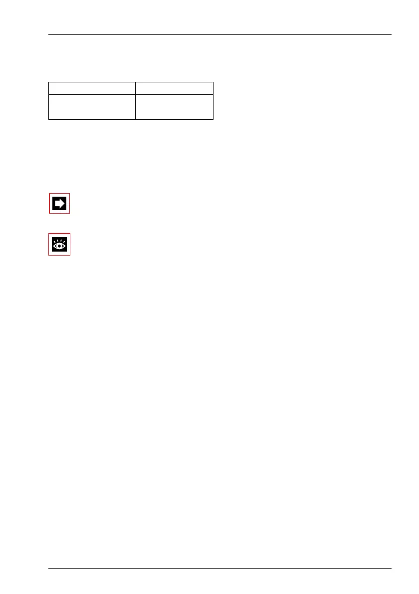
Ambient conditions
Tab. 4.78: Ambient conditions
• When installing: Ensure convection (space for ventilation).
• Avoid excessive dust.
• Avoid exposure to chemicals.
• Avoid direct sunlight.
Note:
If these requirements cannot be met (e.g. outdoor installation), use the
appropriate protective housing.
See also:
"Planning DECT systems", page 611".
8.2.2 Installing the radio units
Do not remove the cover of the radio unit. (Warranty protection will lapse if the
cover is removed)
Fit the mounting bracket (see Fig. 4.90 dimensional drawing for wall mounting).
Observe the minimum distances (see Fig. 4.91).
Position the AD2 socket(s) near the radio unit.
Each radio unit requires one AD2 bus (two optional on the SB-8): Do not connect
any other terminals.
Up to a line length of 660 m (wire diameter 0.5 mm) the SB-4 radio unit can be
powered from the PBX via the AD2 bus. If the line is longer, an outside power sup-
ply is required locally. Special 230 V plug-in power supply units (9...15 VDC,
400 mA) can be supplied for this purpose.
The SB-8 radio unit can be powered from the PBX up to the maximum line length
of 1200 m specified for operation (wire diameter 0.5 mm).
Warning: SB-4 and SB-8 require plug-in power supply units with different contact
assignments, see Tab. 4.79 (the plug-in power supply unit for SB-8 is the same as
the power supply unit for the Office 135 charging bay).
Room class C
Operating temperature 0...40°C
Relative humidity 30...80%

 Loading...


