Operation principle and hardware description 27
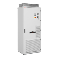
Cabinet layout – bottom entry and exit of cables
The cabinet layout is shown below. See also the next page.
A – Main breaker and power cabling cubicle B – Drive module cubicle
1 Drive control panel - See the next page.
2 Operating switch - -
3 Main switch handle - -
4 Buffering module - -
5 Swing-out frame - -
6 Mounting plate with connection terminals for
cabinet heater (option +G300)
--
7Cabinet fan

 Loading...