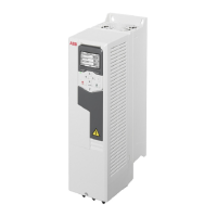
Grounding terminals2T1, 4T2, 6T3 TerminalsCable entriesFrame
size
TMax. wire
size
TMax. wire size
(solid/stran-
ded)
Min. wire size
(solid/stran-
ded)
2)
Ø
1)
Per
cable
type
lbf·ftAWGlbf·ftAWGAWGinpcs
1.164.6414
0.87
3)
1R1
1.164.6414
0.87
3)
1R2
1.124.6414
1.12
4)
1R3
1)
Diameter of the cable entry plate hole.
2)
Note: Minimum wire size does not necessarily have enough current ampacity for full load. Make sure
the installation complies with local laws and regulations.
3)
1/2" conduit. Hole size can be increased to 1.38 in. (1" conduit)
4)
3/4" conduit. Hole size can be increased to 2.0 in. (1-1/2" conduit)
Note: For the tightening torques of the grounding terminals, see sections
Connection procedure, frames R1…R4 (page 186), Connection procedure, frame
R5 (page 194) and Connection procedure, frames R6…R9 (page 198).
R+, R-, UDC+ and UDC- terminalsCable entriesFrame
size
T
Wire range size (stranded/solid)
2)
Ø
1)
Per cable
type
lbf·ftScrew/BoltMaxMin
AWGAWGinpcs
3-phase
U
1
= 200…240 V,
P
n
at
U
n
= 208/230 V, 60 Hz
0.7
3)
10241.111R1
1.1
3)
6201.111R2
2.6
3)
2201.381R3
3.0
3)
1201.731R4
4.1
3)
1201.731R4 v2
11.1M51/061.731R5
22.1M8300 MCM41.971R6
29.5M10500 MCM3/02.441R7
29.5M102×300 MCM2×1/02.442R8
51.6M122×500 MCM2×3/02.442R9
3-phase
U
1
= 440…480 V,
P
n
at
U
n
= 480 V, 60 Hz
Technical data 335

 Loading...