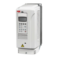
The ACS800-04/U4 and ACS800-04M
16
The ACS800-04M
The ACS800-04M is delivered as non-pre-assembled kits, which provide more
alternatives in assembling the units than the basic ACS800-04.
Example configurations
Motor and brake busbars on the
right-hand long side of the module
and DC busbars on the left-hand
side
Output busbars on the short
side of the module
Motor and brake busbars on the
left-hand long side of the module
and DC busbars on the right-hand
side
Frame size R8
Output busbars on the short
side of the module
Frame size R7
Frame size R7 with bottom exit
(optional top entry busbar
shroud and bottom exit shroud
included). Output busbars are
located at the base of the
module.
Drive Control Unit
(RDCU)

 Loading...