Planning the electrical installation
41
* manufactured before 1.1.1998
** For motors manufactured before 1.1.1998, check for additional instructions with the motor manufacturer.
*** If the intermediate DC circuit voltage of the drive will be increased from the nominal level by resistor braking or
by the IGBT supply unit control program (parameter selectable function), check with the motor manufacturer if
additional output filters are needed in the applied drive operation range.
Note 1: The abbreviations used in the table are defined below.
Note 2: Explosion-safe (EX) motors
The motor manufacturer should be consulted regarding the construction of the motor insulation and
additional requirements for explosion-safe (EX) motors.
Note 3: High-output motors and IP 23 motors
For motors with higher rated output than what is stated for the particular frame size in EN 50347 (2001)
and for IP 23 motors, the requirements of ABB random-wound motor series M3AA, M3AP, M3BP are
given below. For other motor types, see the Requirements table above. Apply the requirements of
range 100 kW < P
N
< 350 kW to motors with P
N
< 100 kW. Apply the requirements of range P
N
>
350 kW to motors within the range 100 kW < P
N
< 350 kW. In other cases, consult the motor
manufacturer.
Note 4: HXR and AMA motors
All AMA machines (manufactured in Helsinki) for drive systems have form-wound windings. All HXR
machines manufactured in Helsinki starting 1.1.1998 have form-wound windings.
Note 5: ABB motors of types other than M2_, M3_, HX_ and AM_
Use the selection criteria given for non-ABB motors.
Note 6: Resistor braking of the drive
When the drive is in braking mode for a large part of its operation time, the intermediate circuit DC
voltage of the drive increases, the effect being similar to increasing the supply voltage by up to 20
percent. The voltage increase should be taken into consideration when determining the motor insulation
requirement.
Example:
Motor insulation requirement for a 400 V application must be selected as if the drive were
supplied with 480 V.
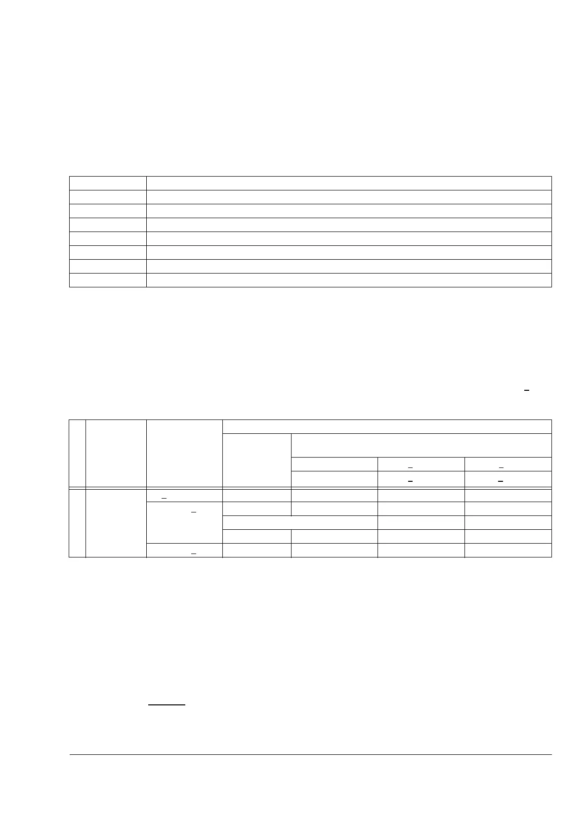
Abbreviation Definition
U
N
nominal voltage of the supply network
Û
LL
peak line-to-line voltage at motor terminals which the motor insulation must withstand
P
N
motor nominal power
du/dt du/dt filter at the output of the drive +E205
CMF common mode filter +E208
N N-end bearing: insulated motor non-driven end bearing
n.a. Motors of this power range are not available as standard units. Consult the motor manufacturer.
Manufacturer
Motor type Nominal mains
voltage (AC line
voltage)
Requirement for
Motor insulation
system
ABB du/dt filter, insulated N-end bearing and ABB common mode
filter
P
N
< 55 kW 55 kW < P
N
< 200 kW P
N
> 200 kW
P
N
< 74 HP 74 HP < P
N
< 268 HP P
N
> 268 HP
A
B
B
Random-
wound M3AA,
M3AP, M3BP
U
N
< 500 V Standard - + N + N + CMF
500 V < U
N
< 600 V Standard + du/dt + du/dt + N + du/dt + N + CMF
or
Reinforced - + N + N + CMF
600 V < U
N
< 690 V Reinforced + du/dt + du/dt + N + du/dt + N + CMF

 Loading...
