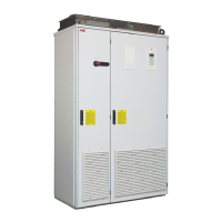
The ACS800-17
36
Operation principle
The line-side and motor-side converters have their own RDCU control units and
control programs. The parameters of each program can be viewed and changed
using one control panel. The converter to be controlled can be selected using the
control panel; see section Controls below.
Line-side converter
The line-side converter rectifies three-phase AC current to direct current for the
intermediate DC link of the drive. The intermediate DC link is further supplying the
motor-side converter that runs the motor.
The LCL filter suppresses the AC voltage distortion and current harmonics.
The IGBT supply module is a four-quadrant switching-mode converter, i.e. the power
flow through the converter is reversible. By default, the converter controls the DC link
voltage to the peak value of the line-to-line voltage. The DC voltage reference can be
set also higher by a parameter. The control of the IGBT power semiconductors is
based on the Direct Torque Control (DTC) method also used in the motor control of
the drive. Two line currents and the DC link voltage are measured and used for the
control.
AC voltage and current waveforms
The AC current is sinusoidal at a unity power factor. The IGBT supply unit does not
generate characteristic current or voltage overtones like a traditional 6- or 12-pulse
bridge does.

 Loading...