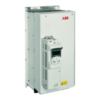
Quick installation guide – ACS850-04
4
Connection procedure
Cabling examples are presented below.
Tightening torques are presented on page 5
and at appropriate points in the text.
• Remove the plastic shroud covering the main
terminals. Lift up with a screw driver from the
corner.
• Connect the twisted shields of the power
cables and separate grounding conductors to
the grounding terminals of the drive module.
• Connect the phase conductors of the supply
cable to the U1, V1 and W1 terminals, and
the phase conductors of the motor cable to
the U2, V2 and W2 terminals. The
recommended stripping length is 16 mm
(0.63”) for frame size E0 and 28 mm (1.1”)
for frame size E.
• Secure the cables mechanically outside the
drive module.
• Cut holes for the installed cables into the
clear plastic shroud to accommodate the
power cables. Press the shroud onto the
terminals.
• Connect the other ends of the power cables.
To ensure safety, pay special attention to
connection of the grounding conductors.
Cabling examples
U2
V2
W2
PE
UDC
-
R+
UDC+
R-
V1
U1
W1
PE
Input power cable Motor cable
Frame size E0: Screw terminal installation
Frame size E: Cable lug installation (16 to 70 mm
2
[AWG6 to AWG2/0] cables)
U1
V1
W1
U2
V2
W2
R-
UDC+
R+
UDC-
PE
8 N·m (5.9 lbf·ft)
Insulate the ends of the
cable lugs with tape or
shrink tube
30…44 N·m
(22…32 lbf·ft)
Input power cable Motor cable
ACS850-04_E0_E_quickguide.book Page 4 Tuesday, February 21, 2012 10:41 AM

 Loading...


