Operation principle and hardware description 33
Hardware of the supply and inverter modules
Frame D7T, D8T and R8i modules are used in single or parallel configurations. D8T and
R8i modules run on wheels, and can easily be removed from the cubicle for cable
installation or service. For moving the D7T modules you need a lifting device.
The quick connector at the back of the D8T and R8i module couples when the module is
inserted into the cubicle. Each parallel-connected module is cabled separately, or
connected by busbars to adjacent modules to reduce the number of cables.
The control electronics of the modules can be powered from an external auxiliary voltage
source. The speed-controlled cooling fan (delivered as standard) is supplied internally
from DC.
Frame D7T and D8T supply modules are controlled by a single BCU control unit installed
separately from the module(s). Frame R8i inverter modules are controlled by a single BCU
control unit installed separately from the module(s). The control unit is connected to each
supply / inverter module by a fiber optic link. The control unit can be powered from a
module, from an external 24 V DC supply, or both for redundancy. The control unit
contains the basic I/Os and slots for optional I/O modules. For descriptions of the I/O
terminals on the BCU control unit, see chapter Control units of the drive (page 337). Other
equipment is primarily installed on separate mounting plates.
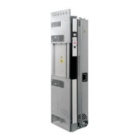
The following figures show the layout of the supply and inverter modules.

 Loading...