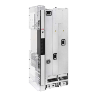
An example installation is shown below.
C
A
A
B
C
D
102 mm (4 in)
L1/U1, L2/V1, L3/W1
T1/U2, T2/V2, T3/W2
E
E
View without enclosure side plate in place.
360-degree grounding at the entry plate for the input power cablesA
Grounding busbar of the input power cabling panelB
360-degree grounding at the entry plate for the output power cablesC
Grounding busbar of the output power cabling panelD
Allowed space for power cables.E
Note: The input and output power cables must fit inside the area marked with diagonal lines to prevent chafing
of the cables when the drive module is inserted into the enclosure.
Installation example with full cabling panels (option +H381) 145

 Loading...