Do you have a question about the ABB BALDOR ACB530 and is the answer not in the manual?
Provides introductory information about the ACB530 variable frequency drive and its functionalities.
Outlines critical safety information regarding high voltages and potential hazards associated with the equipment.
Explains the types of warnings used in the manual to highlight potential dangers and advise on avoidance.
Details safety warnings and instructions pertinent to the installation and maintenance procedures of the drive.
Describes the contents of the drive package and the initial unpacking procedure.
Instructions for checking the drive for damage and verifying its type designation before installation.
Explains the type designation label and provides an example with content explanation.
Provides warnings for safe start-up and operation of the drive.
Defines key terms and abbreviations used throughout the manual for clarity.
Explains how to interpret the drive's type designation and provides a chart for understanding its components.
Details the available enclosure types (IP21/UL Type 1 and IP54/UL Type 12) and their protective features.
Covers checking the installation site, requirements, and general location instructions for the drive.
Lists the necessary tools for installing the drive.
Provides heat loss and air flow data for cooling specifications of the drives.
Details the physical dimensions and weights of the ACB530 drives across different frame sizes and enclosure types.
Outlines the steps for preparing the drive for mounting, including removing covers.
Provides instructions for physically mounting the drive into its enclosure based on IP/UL type.
Describes connecting power cables and addresses compatibility with special power systems.
Instructions for checking the drive's insulation resistance and voltage tests.
Guidance on checking motor compatibility, selecting cables, routing, and operation methods.
Details requirements for grounding the drive and motor for safety and EMC.
Provides an overview of wiring procedures, including conduit/gland kits and wiring requirements.
Specifies requirements for connecting power terminals, including terminal types and torque values.
Details input power specifications and provides guidance on selecting appropriate power cables.
Explains compatibility of brake components, selection of braking resistors, and mandatory circuit protection.
Covers motor connection specifications, cable lengths, thermal protection, and emergency stop devices.
Provides recommendations for fuse selection for short circuit protection on the drive's input power.
A checklist of essential checks to perform before applying power to the drive.
Details specifications for control connections, including analog inputs, digital inputs, and relays.
Provides general rules and recommendations for selecting control cables, including shielding.
Instructions for reinstalling the drive covers after wiring is completed.
Describes different operating modes that change parameter groups for specific applications.
Illustrates how to connect two-wire and three-wire sensors for process control applications.
Introduces keypads, their types, revisions, and firmware versions.
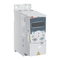
Details the features of the assistant keypad, including its LCD display and navigation keys.
Summarizes the key functions and displays available on the assistant keypad.
Explains the basic status information displayed on the top line of the LCD.
Describes how to operate the keypad using menus and keys for various tasks.
Explains how to navigate and change parameter values using the keypad.
Details how to use the assistants to guide through parameter setup and drive tasks.
Explains how to view and edit parameters that have been changed from default macro values.
Describes how to view the drive fault history and details of stored faults.
Instructions on managing the clock, date, time formats, and daylight saving changes.
Covers exporting and backing up parameters from the drive to the keypad.
Explains how to check and edit parameter settings related to I/O terminals.
Lists and describes various parameters related to start-up data, operating modes, and control types.
Provides instructions for initial drive start-up procedures, including manual and guided methods.
Details how to operate the drive using digital and analog inputs after initial start-up.
Explains the process of performing a motor model calculation for optimizing drive performance.
Describes various program features, including the start-up assistant and its functions.
Explains the differences and usage of local control via keypad versus external control via I/O or fieldbus.
Lists available actual signals that can be displayed or read from the drive.
Explains the motor identification process for optimizing vector control performance.
Describes the drive's capability to maintain operation using motor kinetic energy during supply voltage interruptions.
Details the DC magnetizing feature for improved break-away torque during motor starting.
Explains the DC hold feature for locking the motor rotor at zero speed.
Describes how flux braking enhances deceleration by increasing motor magnetization.
Explains how flux optimization reduces energy consumption and motor noise.
Covers user-selectable acceleration/deceleration ramps and their shape adjustments.
Explains the function to avoid specific motor speeds or bands due to mechanical resonance.
Describes how to define and select positive constant speeds using digital inputs.
Details how to manually adjust controller parameters or use the Autotune function.
Explains the V/F control mode as an alternative to vector control for specific applications.
Describes various protection functions like AI<Min, Panel loss, External fault, Stall, and Thermal protection.
Explains how the drive monitors user-defined variables within set limits, indicated via relay or digital output.
Describes how to prevent parameter adjustment by activating a parameter lock.
Explains the function of the built-in PID controller for process variables like pressure, flow, or temperature.
Details the sleep function for PID control, enabling/disabling logic, and its operation.
Describes how to measure motor temperature using Pt100 or PTC sensors connected to analog input/output.
Explains the jogging function for controlling cyclical machine movements using push buttons.
Covers availability of braking components, selection of braking resistors, and mandatory circuit protection.
Explains how to reset faults and view fault history, including alarm and fault messages.
Emphasizes that only qualified electricians should perform maintenance and reiterates safety notices.
Describes how the drive reports error situations using LEDs, control panel, and parameter bits.
Explains how faults (red LED) and alarms (flashing green LED) indicate abnormal drive status.
Details methods for resetting the drive, including keypad, digital input, fieldbus, or power cycling.
Provides guidance on finding and addressing the root cause of faults using the fault listing table.
Lists routine maintenance intervals recommended by Baldor for the drive.
Instructions for cleaning the heatsink to maintain efficient cooling and prevent overtemperature faults.
Details the expected lifespan of the main cooling fan and procedures for its replacement across different frame sizes.
Explains the function of the internal enclosure fan and procedures for its replacement in different frame sizes.
Discusses the need for capacitor reforming after prolonged storage and information on obtaining guides.
Provides safety warnings and steps for checking power cable connections.
Instructions for cleaning the keypad and changing the battery in the assistant keypad.
Lists the standards to which the drive complies, identified by marks on the type designation label.
Details applicable standards and their compliance, including CE and C-Tick markings.
Lists the environmental requirements for the ACB530 drive, including altitude, temperature, and humidity.
Specifies the materials used for the drive enclosure, package, and disposal considerations.
States the drive's efficiency at nominal power level.
Provides a comprehensive list of ACB530 parameters categorized by group, including default values and ranges.
Defines Electromagnetic Compatibility (EMC) and specifies categories for drives and environments.
Outlines drive compliance with EMC requirements for first and second environments, including motor cable length.
Details motor cable requirements, including conductor layout and effective shield construction for EMC compliance.
Lists US patents protecting the product and provides information on branch circuit protection.
Lists available standard options and kits for the ACB530, including I/O, keypad, and communication options.
Details specific optional equipment and accessories like digital input interfaces, mounting kits, and communication adapters.
Briefly describes the chapter's content regarding drive control via communication networks using embedded fieldbus.
Explains how the ACB530 can be controlled via serial communication protocols and outlines basic control interfaces.
Lists key questions to address during network planning for drive communication.
Provides instructions for the mechanical and electrical installation of the embedded fieldbus (EFB) using RS485.
Details the steps for activating and configuring serial communication for the embedded fieldbus using Modbus.
Explains how to configure drive functions for fieldbus control, including start/stop, references, and system control.
Describes pre-defined feedback signals and actual value scaling for communication with the drive.
Covers fault handling, serial communication diagnostics, and troubleshooting common diagnostic situations.
Provides technical data for the Modbus protocol, including function codes and mapping.
Details the ABB Drives profile, including control word and status word information for FBA modules.
Explains the function and types of fieldbus adapters available for the ACB530.
Outlines the basic control interface between fieldbus systems and the drive, including output and input words.
Describes the control word for drive management via fieldbus, dependent on protocol and profile used.
Provides detailed technical data for the ABB Drives profile, including status words and state diagrams.
Lists sales offices in various states across the United States.
Lists sales offices in Canada, Mexico, and other international locations.
| Model | ACB530 |
|---|---|
| Frequency | 50/60 Hz |
| Enclosure Rating | IP20 |
| Category | Controller |
| Manufacturer | ABB |
| Protection Features | Overcurrent, Overvoltage, Short Circuit, Overtemperature |
| Communication Interface | Modbus RTU |
| Humidity | 5% to 95% (non-condensing) |
| Storage Temperature | -20 to 70°C |

