7
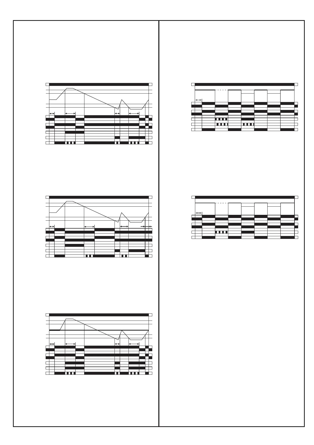
IV Function diagrams
21-22
21-24
L1, L2, L3
11-12
11-14
L1, L2, L3 L1, L2, L3 L1, L2, L3 L1, L2, L3L1, L3, L2 L1, L2 L1
L3 L2, L3t
s
2CDC 252 003 F0212
F: red LED
R: yellow LED
Measured value
t
s
= start-up delay fixed 500 ms
25-26
25-28
L1, L2, L3
15-16
15-18
L1, L2, L3 L1, L2, L3 L1, L2, L3 L1, L2, L3L1, L3, L2 L1, L2 L1
L3 L2, L3t
s
2CDC 252 094 F0207
F1: red LED
F2: red LED
R/T: yellow LED
Measured value
t
s
= start-up delay fixed 200 ms
L1, L2, L3
15-16
15-18
L1, L2, L3 L1, L2
L3
t
s
t
v
t
v
<t
v
25-26
25-28
2CDC 252 092 F0207
F1: red LED
F2: red LED
R/T: yellow LED
Measured value
Unbalance
Unbalance -Hyst.
Unbalance +Hyst.
Unbalance
t
s
= start-up delay fixed 200 ms
t
v
= adjustable tripping delay
L1, L2, L3
15-16
15-18
> U
> U - 5 %
< U + 5 %
< U
t
s
t
v
t
v
<t
v
25-26
25-28
2CDC 252 090 F0207
F1: red LED
F2: red LED
R/T: yellow LED
Measured value
t
s
= start-up delay fixed 200 ms
t
v
= adjustable tripping delay
a) ON-delayed
over- and undervoltage monitoring
CM-PSS, CM-PVS
b) OFF-delayed
over- and undervoltage monitoring
CM-PSS, CM-PVS
c) ON-delayed
phase unbalance monitoring
CM-PAS
d) Phase sequence and phase failure monitoring
CM-PAS, CM-PSS, CM-PVS
e) Phase sequence and phase failure monitoring
CM-PFS
25-26
25-28
L1, L2, L3
15-16
15-18
> U
> U - 5 %
< U + 5 %
< U
t
s
<t
v
<t
v
t
v
2CDC 252 091 F0207
F1: red LED
F2: red LED
R/T: yellow LED
Measured value
t
s
= start-up delay fixed 200 ms
t
v
= adjustable tripping delay
/
0
1
2
3
4
5
6
7
8
9
/
0
1
2
3
4
5
6
7
8
9
/
0
1
2
3
4
5
6
7
8
9
/
1
3
6
4
5
7
8
/
1
3
4
5
7
8