4.7.5 Removal of motor, axes 4, 5 and 6
Location of motors
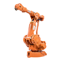
The motors, axes 4, 5 and 6, are located as shown in the figure below. (The figure
shows the IRB 4400.)
The motor and the drive gear of each axis constitute one unit.
A more detailed view of the component and its position may be found in chapter
Exploded views, in Product manual, spare parts - IRB 4400.
xx0300000164
Motor unit, axis 4A
Motor unit, axis 5B
Motor unit, axis 6C
Attachment screws and washers, motorD
Connection boxE
Required equipment
NoteArt. no.Equipment, etc.
Content is defined in section Stand-
ard tools on page 291.
3HAC17594-1Standard toolkit
These procedures include references
to the tools required.
Other tools and procedures may
be required. See references to
these procedures in the step-by-
step instructions below.
See chapter Circuit diagram on
page 297.
Circuit diagram
Continues on next page
Product manual - IRB 4400 233
3HAC022032-001 Revision: Q
© Copyright 2004-2018 ABB. All rights reserved.
4 Repair
4.7.5 Removal of motor, axes 4, 5 and 6

 Loading...