Mechanical installation
Installing gear racks
2-20 3HEA 800 970-001 Rev. D, Mars 2006
Installation and operation
IRBT 4003S
2.3.6 Installing gear racks
Follow the instructions below to assemble the gear racks.
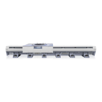
Bredd höjdmått_4003_90.emf
Figure 12 Placement of the prism on the linear guides
Item Description
1 Top machined surface of carriage
2 Ball element
3 Linear guide
Action Info/Illustration
6. Place the prism above the horizontal
linear guide and on the upper edge of the
vertical linear guide with an angle bracket.
Values from the robot's center point and
the robot's Z-zero.
With this measurement method, the track
motion can be installed with accuracy of
± 0.05 mm compared to the virtual
geometry.
 Loading...