LIST OF FIG URES
List of Figures
Figure 1: Example of using FC610 in a 3-phase feeder ......................................................................... 6
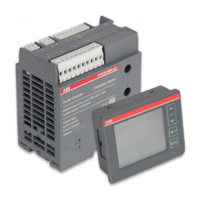
Figure 2: FC610 basic unit with HMI MP56, MP53 .................................................................................. 7
Figure 3: DIN-rail mounting and removing of FC610 basic unit ......................................................... 8
Figure 4: Installation of HMI MP53/56 ..................................................................................................... 8
Figure 5: Installation dimension and DIN-rail mounting ..................................................................... 9
Figure 6: Screw mounting of FC610 basic unit ..................................................................................... 10
Figure 7: Front panel cut-out dimension of MP53 ................................................................................ 10
Figure 8: Front panel cut-out dimension of MP56 ............................................................................... 10
Figure 9: FC610 basic unit terminals description................................................................................. 11
Figure 10: FC610 basic unit top view terminal layout .......................................................................... 12
Figure 11: 24 VDC power output ............................................................................................................... 13
Figure 12: Relay output connection ......................................................................................................... 13
Figure 13: DIs supplied by internal 24 VDC ............................................................................................ 13
Figure 14: DIs supplied by external 24 VDC ........................................................................................... 14
Figure 15: RS485 connection ..................................................................................................................... 14
Figure 16: Voltage measurement direct connection ............................................................................ 15
Figure 17: Voltage measurement connection via PT ............................................................................ 15
Figure 18: Current measurement single phase connection ............................................................... 16
Figure 19: Current measurement 3phase, IT network connection ................................................... 16
Figure 20: Current measurement 3phase+N, TN/TT network connection ..................................... 16
Figure 21: FC610 product features ........................................................................................................... 17
Figure 22: Four-quadrant representation of active and reactive power and energy ................... 19
Figure 23: Example of voltage dip curve U1- the event completes within 120 samples time ... 30
Figure 24: Example of voltage dip curve U1 - the event longer than 120 samples time ............. 30
Figure 25: Example for LVS Digital integration with FC610 via Modbus RTU ............................... 32
Figure 26: Example for LVS Digital integration with FC610 via Modbus TCP (MS572) ............... 32
Figure 27: MP53 Operator Panel Figure 28: MP56 Operator Panel .... 33
Figure 29: Main display page ................................................................................................................... 34
Figure 30: Navigate through display groups ........................................................................................ 35
Figure 31: Navigate through display pages under each group ......................................................... 36
Figure 32: How to change default password ......................................................................................... 41
Figure 33: Turn off the voltage, frequency display group ................................................................. 42
Figure 34: Change the hysteresis value ................................................................................................. 45
Figure 35: Read firmware version ........................................................................................................... 47
Figure 36: Configuration of FC610 .......................................................................................................... 48
List of Tables
Table 1 Alarm messages and description.............................................................................................. 39

 Loading...