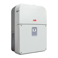
Hardware description 25
Layout drawing
No. Description No. Description
1 First cover 10 Control board terminals
2 Display and keypad 11 Internal fan
3 Second cover 12 External fans, 2 pcs (one on each side)
4 Control unit 13 Cable glands for control cables, 3 pcs
5 Monitored input surge protection
devices (-SX)
14 DC switch (-S & -SX)
6 Type designation label 15 AC output terminal
7 DC input cover 16 Wall mounting plate
8 DC input (standard & -S): Screw
terminals and cable glands
17 Supplied accessories: Documentation,
AC connector housing, eye bolts, etc.
9 DC input (-SX): PV quick connectors
and monitored string fuses, 16 pcs
1
2
4
6
5
7
10
15
13
3
12
17
14
11
16
8
9
 Loading...


