34 Installation | Installation and commissioning manual | 1SFC132081M0201
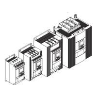
4.2.3 Minimum enclosure dimensions
In applications where the Softstarter is installed in an
enclosure, use these minimum enclosure dimensions. See
Figure 4.5 and Table 3 and 4.
Table 3 Minimum enclosure dimensions (IEC)
IEC
Minimum enclosure dimensions
Softstarter type W (mm) H (mm) D (mm)
PSTX30...105 508 508 305
PSTX142...170 508 508 305
PSTX210...370 762 914 305
PSTX470...570 914 1219 405
PSTX720...840 914 1524 405
PSTX1050...1250* 914 1524 405
*PSTX1250 Recommended fan capacity 230m3/h
Table 4 Minimum enclosure dimensions (UL)
Minimum enclosure dimensions
Softstarter type W (in) H (in) D (in) Min number of
latches
PSTX30...105 20 20 10 2
PSTX142...170 20 20 12 2
PSTX210...370 30 24 12 7
PSTX470...570 36 48 16 8
PSTX720...840 36 60 16 8
PSTX1050...1250* 36 60 16 8
*PSTX1250 Recommended fan capacity 230m3/h
4.2.4 Maximum installation angle
Make sure that the distances to the walls are
sufficient. Use the installation angle given in
Figure.
4.2.5 Dimensions and drilling plan
For dimensions and drilling plan see chapter 3.2.6
Dimensions. Drilling plan is also printed on the box.
WARNING
Risk of damage to property. Ensure that no
liquids, drilling particles, dust or conductive parts
enter the Softstarter.
WARNING
When the enclosure is too small and/or you do
not obey the instructions, the Softstarter can
overheat or not operate correct.
4.2.6 Movable keypad
If you remove the PSTX keypad, connect it with the
included 3 meter cable for serial communication and
power supply. Connect the cable to the network port on
the front of the Softstarter. To remove the keypad, push
the lock with a screwdriver, see
1
and
2
in Figure 4.8.
Figure 4.5
Minimum enclosure size
H
W
D
1SFC132081M0201
Figure 4.6
Airflow
1SFC132081M0201
Figure 4.7
Maximum mounting angle
30
O
30
O
30
O
30
O
1SFC132081M0201
2
1
Figure 4.8
Detach the keypad
1SFC132081M0201
4
 Loading...