The circuit breaker is
closed and the close
coil is disconnected or
broken.
In this case, only the opening operation is avail-
able; open the circuit breaker (the ready LED will
be turned off) and check the closing coil circuit.
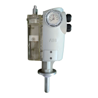
Unplug the magnetic actuator from the plug to the
left of the mechanism (MA). There are two
Phillips head screws that keep the plug held
together. The top two wires are red and the
bottom two wires are blue. The top red (43) and
top blue (45) wire go to the "On" (close) coil. The
coil should read approximately 0.3 ohms.
The auxiliary supply
voltage has been
turned off.
If the circuit breaker is closed you can perform a
CO-operation; connect the auxiliary supply.
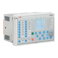
Check pins 2 and 3 on KM1003 to confirm proper
input voltage is applied.
The capacitor bank is
charging during start
up or after an opera-
tion.
The opening
command is not
performed
The opening
command is not
performed
The opening coil is
broken or damaged.
In this case, only the closing operation is avail-
able; open the circuit breaker (the ready LED will
be turned off) and check the closing So circuit.
Disconnect the magnetic actuator from the plug
to the left of the mechanism. There are two
Phillips head screws that keep the plug held
together. The top two wires are red and the
bottom two wires are blue. The top red (43) and
top blue (45) wire go to the "On" (close) coil. The
coil should approximately 0.3 ohms.
The capacitor bank is
not connected.
Check the capacitor bank circuit. Verify the
capacitors are connected to the control board.
Ensure that there is 80 VDC across KM1002 ter-
minals 1 and 3.
No external opening
input is connected.
Verify opening input is wired.
The control panel is
either damaged or not
connected correctly.
Verify the control panel 6-pin plug is plugged into
KM1007.
All indication output
contacts are open
The voltage on the
capacitor bank is
under 46 VDC.
Connect the auxiliary power supply voltage.

 Loading...