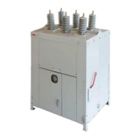
The circuit breaker
opens if the
auxiliary supply is
switched off
The UV function is
active and the
auxiliary supply is
parallel to this input.
Either disable the UV function or connect to a dif-
ferent voltage source.
The energy failure
auto trip function is
enabled.
If possible, disable the function via I1004-1.
Switch 1 should be in the off position.
Apx Table 7 Breaker Troubleshooting Guide
12. INSTRUCTIONS FOR CHANGING OUT A CONTROL
BOARD
Because of the risk of death or serious bodily injury, capacitors must be fully
discharged prior to troubleshooting.
1. Disconnect the source power to the R-MAG.
2. Remove the two #4 screws holding on the push button plate and let it hang down.
3. Remove the four .250 X 20 screws from the corners of the CONTROL BOARD cover.
4. With the cover removed, verify the voltage input to the board is off by measuring the voltage
at KM1003 terminals 2 and 3. It should be zero.
5. Before proceeding, discharge the capacitors by placing jumpers on KM1003 pins 4 and 5.
The time constant is 66 minutes. A smaller external resistor can be used for a quicker
discharge, but the discharge current should be restricted to 10 amperes maximum. This
means that no lower than 10 Ω 25 watt external resistance should be used to perform
capacitor discharging. When discharging with an external capacitor, connect to pins 2 and 3
on KM1002.
6. After the capacitors are discharged, take a small screwdriver and remove the capacitor
wires from KM1002 pins 1, 2, 3 and 4. Note how they are connected since they will be
reinstalled on the new board.
7. Remove five plugs: KM1001, KM1002, KM1003, KM1004 and KM1005. To remove, loosen
hold down screws from each plug.
8. Remove plug for push button plate. This is not held by retainers.
9. Remove four .250-20 nut, lock and flat washer from the four corners. Keep the three rubber
washers behind each screw.

 Loading...