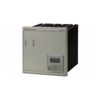
Auxiliary unit for REG216/316*4 for 100%
stator and rotor earth fault protection
REX010/011
1MRB520123-Ben
Page 3
ABB Switzerland Ltd
Utility Automation
The coding is achieved by alternating the
transmission of the square wave with a quies-
cent period, as seen in Fig. 3.
Fig. 3
The REG216/316*4 evaluates and compares
the measured injected voltage with the refer-
ence voltage during the transmitting period.
In the quiescent period the evaluation of pos-
sible interferences is active, ensuring the cor-
rect protection response. The injection trans-
former REX011 is equipped with a contactor,
type P8. In the case that the earth fault current
exceeds 5 A the contactor will open the input
circuit to the injection unit to protect it
against high voltages during earth faults near
the generator terminals. The 95% function is
always active and will detect any earth faults.
The resistors R
ES
, R
PS
are used to provide
high-resistance earthing of the generator
neutral point and for coupling the injection
signal to R
PS
as well as the measurement sig-
nal to R
ES
. A similar arrangement applies for
the generator rotor where coupling is made
with the resistors R
ER
and R
PR
; however, two
additional capacitors C
1
and C
2
are required.
There are three connection variants for the
stator and two for the rotor earth fault protec-
tion.
Software Three protection functions are available in the
REG216/316*4 library:
- 100% Stator earth fault
protection Stator EFP
- Rotor earth fault protection Rotor EFP
- 95% Stator earth fault
protection Overvoltage U>
During the transmitting period, the digital fil-
ter algorithms are calculating the instanta-
neous earth fault resistance from the input
signal pairs Uis, Ui and Uir, Ui respectively.
During the quiescent period the filtered sig-
nals Uis and Uir are examined for interfer-
ence from the protected object or the connec-
ted network. This examination is used to vali-
date the previous calculation of the earth fault
resistance.
The reference signal Ui is continuously
supervised with respect to amplitude and fre-
quency. This ensures that the injection signal
is correct and that it has the correct frequency.
The primary earth connection of the protected
machine is checked through evaluation of the
capacitive component of the earth fault cur-
rent during the transmitting period.
100% Stator earth fault protection function
This function consists of an alarm level and a
trip level with corresponding signalling and
tripping outputs.
It is possible to compensate for a second
high-resistance earth to neutral point within
the protected zone by including the monitor-
ing of the generator circuit breaker status.
The function is capable of measuring the ef-
fective value of R
ES
and of the transformation
ratio of the voltage transformer while the ma-
chine is at standstill. This allows optimizing
the function with the actual parameters of the
protected machine.
Alarm and trip levels are entered and read out
in kΩ.
Settings:
Alarm level 100 Ω to 20 kΩ
Delay 0.2 s to 60s
Trip level 100 Ω to 20 kΩ
Delay 0.2 s to 60 s
R
ES
400 Ω to 5 kΩ
Number of neutral points
2
R
ES
-2. neutral point 900 Ω to 30 kΩ
Reset ratio 110% (with
settings of <10 k
Ω
)
120% (with
settings of >10 k
Ω
)
Accuracy 100 Ω to 10 kΩ:
<±10%
0 to 100 Ω, 10 kΩ
to 20 kΩ: <±20%
Operating time 1.5 s
Machine and system parameters:
- Max. earth fault
current l
0
<20 A (recom-
mended l
0
≤5 A)
- Stator earth
capacitance 0.5 µF to 6 µF

 Loading...