Where:
Uph is phase to earth voltage at the relay point
Iph is phase current in the faulty phase
3I0 is earth fault current
Z1 is positive sequence impedance
Z0 is zero sequence impedance
Z
0m
A B
Z< Z<
IEC09000250_1_en.vsd
IEC09000250 V1 EN
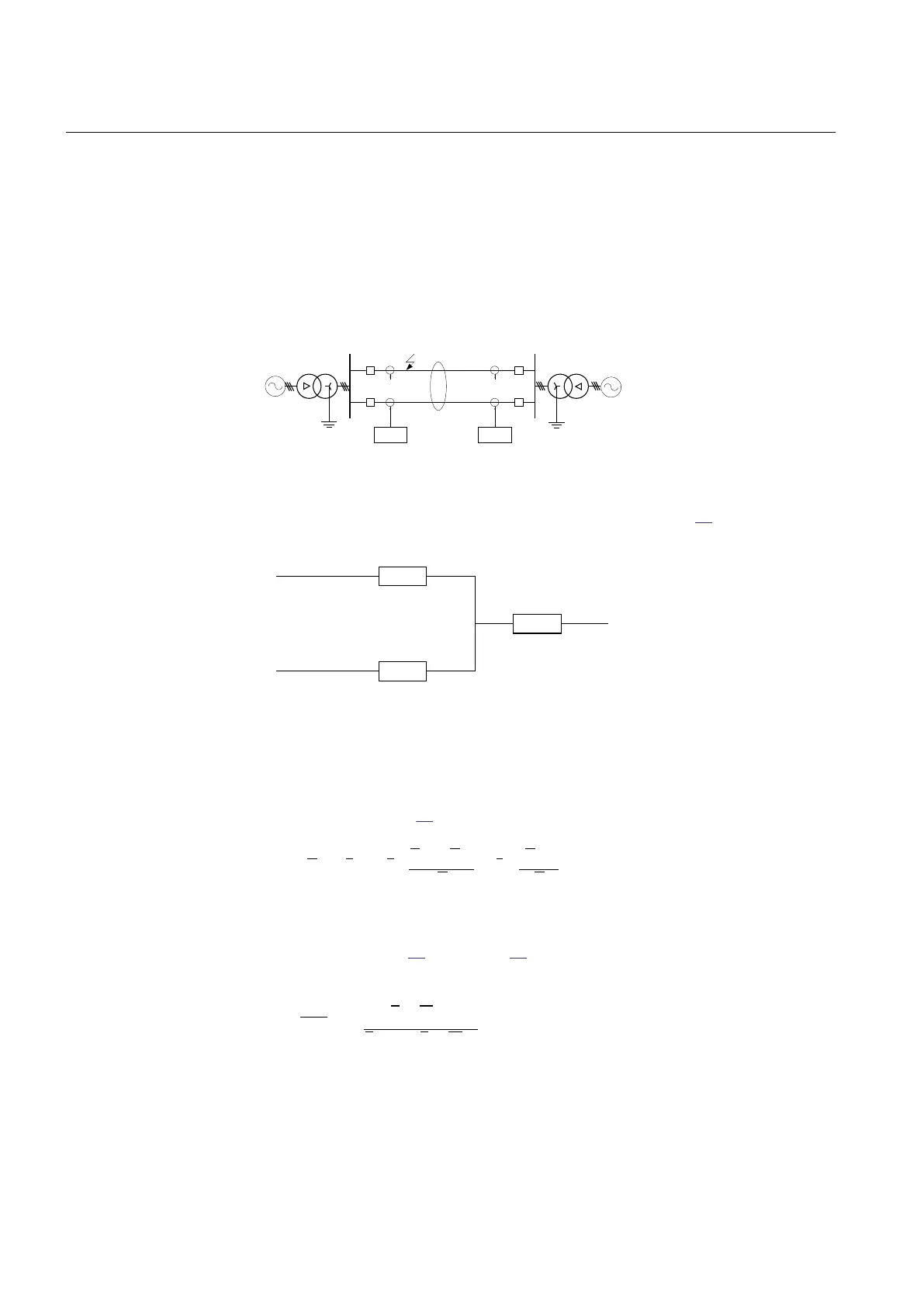
Figure 84: Class 1, parallel line in service
The equivalent circuit of the lines can be simplified, see figure 85.
A
B
C
Z
0m
Z
0m
Z
0
-
Z
0m
Z
0
-
IEC09000253_1_en.vsd
IEC09000253 V1 EN
Figure 85: Equivalent zero sequence impedance circuit of the double-circuit,
parallel, operating line with a single phase-to-earth fault at the remote
busbar
When mutual coupling is introduced, the voltage at the relay point A will be changed
according to equation 42.
0 0
0
0 1
1 3 3
3 1 3 1
m
L L
ph p
ph L
L L
Z
Z Z
U Z I I I
Z Z
æ ö
-
= × + × +
ç ÷
× ×
è ø
IECEQUATION1276 V3 EN (Equation 42)
By dividing equation 42 by equation 41 and after some simplification we can write the
impedance present to the relay at A side as:
3 0
1 1
3 0
æ ö
×
= +
ç ÷
+ ×
è ø
L
I KNm
Z Z
I ph I KN
EQUATION1277 V3 EN (Equation 43)
Where:
KNm = Z0m/(3 · Z1L)
Section 8 1MRK 502 071-UEN -
Impedance protection
196 Generator protection REG670 2.2 IEC and Injection equipment REX060, REX061, REX062
Application manual

 Loading...


