Uinj
Rshunt
~
Step- up
Transformer
R
O
T
O
R
E
F
REX060/
RIM module
REG670
4
5
6
3
1
7
I
U
Generator
R
N
2
REX061
Generator Protection Panel
R C
IEC11000014-4-en.vsd
U>
8
IEC11000014 V1 EN
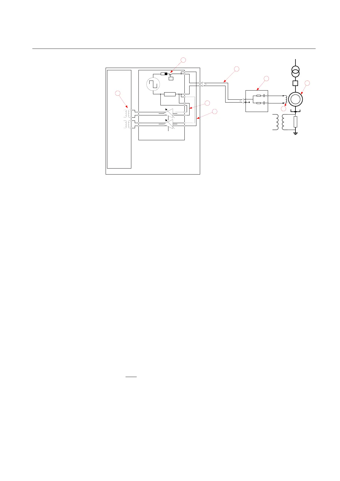
Figure 155: Connection of REX060 for rotor earth fault protection
1 Generator unit consisting of a synchronous generator and a step-up transformer
2 Generator field winding
3 Capacitor coupling unit which is used to provide insulation barrier between rotor circuit and injection
equipment
4 Cable used to inject the square-wave signal into the rotor circuit
5 Connection for measurement of injected current. This signal is amplified in REX060 before it is
passed on to IED for evaluation.
6 Connection for measurement of injected voltage. This signal is amplified in REX060 before it is
passed on to IED for evaluation.
7 Two VT inputs into IED which are used to measure injected current and voltage
8 Protection for excessive over-voltages posed by generator. REX060 can withstand without damage
maximum voltage of 120V and when used together with REX062 up to 240V.
The measured impedance Z
Measured
is calculated by the complex equation:
GUID-20ADF3F6-6A89-4B5F-B0DA-9740C4FD5482 V2 EN
Where:
IECEQUATION17021 V1 EN
1MRK 502 071-UEN - Section 8
Impedance protection
Generator protection REG670 2.2 IEC and Injection equipment REX060, REX061, REX062 293
Application manual

 Loading...


