28
1MRS 752137-MUM
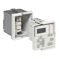
Combined Overcurrent and Earth-Fault Relay
Operator’s Manual
REJ 525
The secondary testing described in this manual is based on the relay’s setting values
during normal operation. (If necessary, the secondary testing can be extended by
testing the protection stages throughout their setting ranges.)
All setting values to be altered during the test procedure have to be read and stored
prior to the tests.
To enable secondary testing, the relay has to be disconnected, either by
disconnecting the terminal blocks or by fitting a test plug on the relay.
Equipment required for testing:
• adjustable voltage transformer 0...260 V, 1 A
• current transformer
• ammeter, accuracy ±0.5%
• stop watch or counter for time measurement
• ac/dc voltage source for the auxiliary supply
• switches and indicator lamps
• supply and pilot wires
• calibrated multimeter
The secondary current is to be selected on the basis of the rated current, 0.2 A, 1 A
or 5 A, of the relay energizing input to be tested.
1RWH
For the limited current carrying capacity of the wiring, terminals and measuring
transformers of the relay, refer to section Technical data in the Technical Reference
Manual.
Danger!
Do not open the secondary circuit of a current transformer during any phase of
the testing when the primary circuit is live. The high voltage generated by an
open CT secondary circuit may be lethal and damage instruments and
insulation.

 Loading...