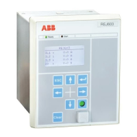
Self-powered feeder protection
15 ABB
Table 26. High- set earth-fault protection, stage I0>> / 50N
Setting range of pick-up current ‘I0 >>’
External earth measurement (through CBCT or residual connection) :
0.01...12.5 x In in steps 0.001, infinite
Internal earth measurement : 0.1...12.5 x In in steps 0.001, infinite
External earth measurement : ± 3.0% x In for value < 1.2 In , ± 3.0%
x I for value ≥ 1.2 In
Internal earth measurement : ± 9.0% x In for value < 1.2 In , ± 9.0% x
I for value ≥ 1.2 In
Definite time, Instantaneous
Operate time delay (DMT) ‘t0 >>’
0.04...64 s in steps of 0.01
Operation time accuracy
1)
External earth measurement : ± 2.0% of set value or ± 30 ms
Internal earth measurement : ± 10.0% of set value or ± 30 ms
1)
Operation time accuracy for protection functions when relay is in energised condition.
Table 27. Transformer inrush detection, 3I2f> / 68
0.2...32 x In, in steps of 0.01
10%...50%, in steps of 1%
Table 28. Thermal overload protection, 3Ith> / 49
Initial thermal level of apparatus 0
Reference current leading to thermal
calculation “Ib”
0.1 … 1.5 x In, in steps of 0.1
Heating time constant of object ‘𝜏′
1.0…300 min, in steps of 1.0
Cooling time constant of object ‘𝜏
↓𝑠
‘
1.0…300 min, in steps of 1.0
Options for calculating thermal value
during power interruption, powerOFF
3% of 5 time constant or ± 30s
1)
Options for calculating thermal image during power interruption shall be as below
1 = On restoration of power, new value of current after power on will be considered to calculate new value of thermal image for
interruption period Δt.
2 = On restoration of power, new value of thermal image is calculated for interruption period Δt considering that current has
remained constant value during power interruption.
3 = Power interruption of the relay assumes no change of thermal image during interruption period.
4 = Power interruption of the relay resets the thermal image to the set value defined by setting
0.

 Loading...