1MRS 750942-MUM
Combined Overvoltage and Undervoltage Relay
Technical Reference Manual
REU 523
13
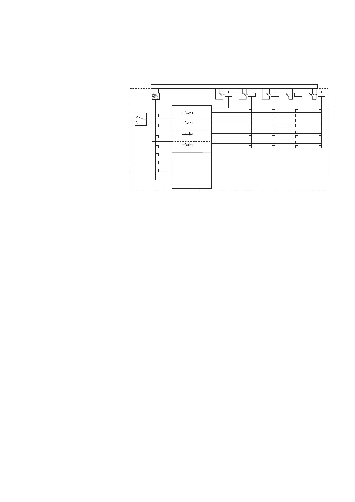
4.1.3. Configuration
The figure below illustrates how the start, trip and binary input signals can be
configured to obtain the required protection functionality.
)LJ 6LJQDOGLDJUDP
The functions of the blocking and start signals are selected with the switches of
switchgroups SGF, SGB and SGR. The checksums of the switchgroups are found
under “SETTINGS” in the HMI menu. The functions of these switches are explained
in detail in the corresponding SG_ -tables.
17 18
X2.1
13 14 15
10 11 12
7 8 9
3 45 6
SDiag_U5_3
3U>
3U>>
3U<
3U<<
4
5
U12
U23
U31
6
7
8
1
2
3
4
4
4
4
4
4
4
3
3
3
3
3
3
3
3
2
2
2
2
2
2
2
2
1
1
1
1
1
1
1
1
IRF
START
TRIP
START
TRIP
SGR5
SGR6
SGR7
SGR8
START
START
TRIP
TRIP
SGB1
SGB1
SGB1
SGB1
SGB1
SGB1
SGB1
SGR1
SGR2
SGR3
SGR4
SGF1...SGF4
PO1PO2SO1
IRF
SO2
BI
4
SGB1
Blocking of stage U<<
Blocking of stage U<
Blocking of stage U>>
Blocking of stage U>
INDICATIONS CLEARED
OUTP. CONT. UNLATCHED
AND INDICATIONS CLEARED
MEMORIZED VALUES AND
INDIC.CLEARED; OUTPUT
CONTACTS UNLATCHED
SWITCHGROUP SELECTION

 Loading...

