28
1MRS 750942-MUM
Combined Overvoltage and Undervoltage Relay
Technical Reference Manual
REU 523
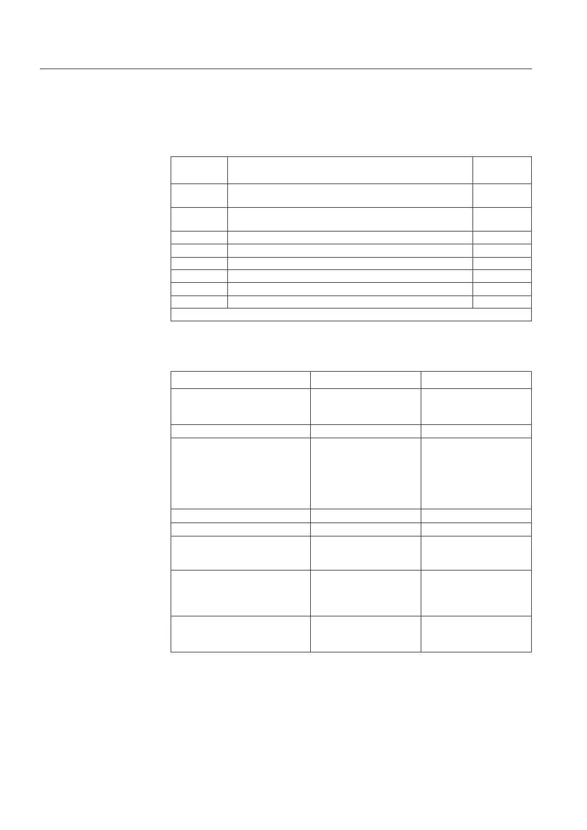
Non-volatile memory settings
The table below presents data which can be configured to be stored in the
non-volatile memory. All of the functions mentioned below can be selected
separately with switches 1...5 in “MEMORY SETTINGS”.
4.1.4.7. Technical data on protection functions
Table 4.1.4.6-9 Memory settings
Switch Function
Default
setting
1 • 0 = alarm indication messages and LEDs will be cleared
• 1 = alarm indication messages and LEDs will be retained
1
2 • 1 = information on the “NUMBER OF STARTS” of the
protection stages will be retained
1
3 • 1 = disturbance recorder data will be retained 1
4 • 1 = event codes will be retained 1
5 • 1 = recorded data will be retained 1
6Not in use 0
7Not in use 0
8Not in use 0
checksum 31
Table 4.1.4.7-1 Stages U> and U>>
Feature Stage U> Stage U>>
Set start value
• at definite-time and IDMT
characteristic
0.60...1.40 x U
n
0.80...1.60 x U
n
1
)
)
Start time, typical 60 ms 50 ms
Time/voltage characteristics
• definite time
operate times t> and t>> 0.06...600 s 0.05...600 s
• IDMT
time multipliers k> and k>>
A-curve
B-curve
0.05...2.00
A-curve
B-curve
0.05...2.00
Resetting time, typical
70 ms 70 ms
Drop-off/pick-up ratio 0.95...0.99 0.97
Operate time accuracy at
definite-time characteristic
±2% of the set start value
or
±25 ms
±2% of the set start value
or
±25 ms
Operate time accuracy at
IDMT characteristic
±25 ms or the accuracy
appearing when the
measured voltage varies
±3%
±25 ms or the accuracy
appearing when the
measured voltage varies
±3%
Operation accuracy
• definite-time and IDMT
characteristic
±1.5% of the set start value ±1.5% of the set start value

 Loading...

