1MRS 750942-MUM
Combined Overvoltage and Undervoltage Relay
Technical Reference Manual
REU 523
29
1)
The stage can be set out of operation in SGF. This state will be indicated by dashes on the LCD and
by “999” when parameters are read via the SPA bus.
4.1.5. Indicator LEDs and alarm indication messages
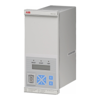
The operation of the REU 523 can be monitored by means of three indicators on the
front panel of the relay: a green READY indicator LED, a yellow START indicator
LED and a red TRIP indicator LED (refer to the Operator’s Manual for a more
thorough presentation).
In addition, in case of an alarm from a protection stage, a text message will appear
on the LCD.
The messages on the LCD have a certain priority order. If different types of
indications are activated simultaneously, the message with the highest priority will
appear on the LCD.
The priority order of the messages:
1. CBFP
2. TRIP
3. START
Table 4.1.4.7-2 Stages U< and U<<
Feature Stage U< Stage U<<
Set start value
• at definite-time and IDMT
characteristic
0.30...1.20 x U
n
0.30...1.20 x U
n
1
)
)
Start time, typical 80 ms 50 ms
Time/voltage characteristics
• definite time
operate times t< and t<< 0.10...600 s 0.10...600 s
• IDMT
time multipliers k< and k<<
C-curve
0.10...2.00
C-curve
0.10...2.00
Resetting time, typical 70 ms 70 ms
Drop-off/pick-up ratio 1.01...1.05 1.03
Operate time accuracy at
definite-time characteristic
±2% of the set start value
or
±25 ms
±2% of the set start value
or
±25 ms
Operate time accuracy at
IDMT characteristic
±25 ms or the accuracy
appearing when the
measured voltage varies
±3%
±25 ms or the accuracy
appearing when the
measured voltage varies
±3%
Operation accuracy
• definite-time and IDMT
characteristic
±1.5% of the set start value ±1.5% of the set start value
• positive-phase-sequence with
definite-time and IDMT
characteristic
±5% of the set start value

 Loading...