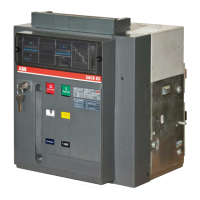
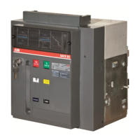
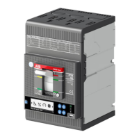
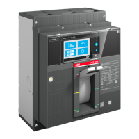
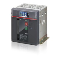
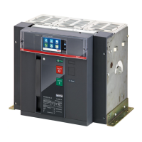
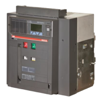
Product Description
ii
1HSB515432-100 en rev2
FIGURES
Figure 1-1. Operating mechanism ..................................................................... 1
Figure 1-2. Normal operating mode. ................................................................. 2
Figure 1-3. Opening operation. ......................................................................... 3
Figure 1-4. Closing operation. .......................................................................... 4
Figure 2-1. Drive unit. ....................................................................................... 5
Figure 2-2. Interlocking mechanism. ................................................................ 5
Figure 2-3. Catch gear. ...................................................................................... 6
Figure 2-4. Closing and Opening dashpots. ...................................................... 6
Figure 2-5. Limit switch with auxiliary contact. ............................................... 7
Figure 2-6. Heater element. ............................................................................... 8
 Loading...
