Assembly Instructions
Assembly
1HSB435410-2 enrev1 21
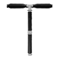
Figure 4-15. Assembling the pull-rods.
Item
1 Coupling link (right-hand thread), pole A1
2 Locking nut (right-hand thread)
3 Locking nuts (left-hand thread), 2 pcs.
4 Pull-rod, pole A1-B1
5 Coupling link (left-hand thread), pole B1
6 Operating lever
7 Locking screw and square washer
8 Cylindrical pin
Pole A1
Pole C1
Pole B1
4
1
3
2
7, 8
6
5
7, 8
B10134
 Loading...