Assembly Instructions
Electrical connections
1HSB435410-2 enrev1 25
5. Electrical connections
5.1 Connection of the operating mechanism
Operation and signal cables are routed through the connection flange at the bottom
of the cabinet. Fit the flange with a suitable cable gland for the cable in question.
Connect the cables to the terminal blocks in accordance with the applicable wiring
diagram. The terminal blocks are of a snap-in type and are designed both for
through wiring with termination of a stranded conductor with a cross section of
max. 4 mm
2
, and disconnectable block with termination of a stranded conductor
with a cross section of max. 6 mm
2
intended for motor circuits, AC circuits and
supply circuits.
Connect the earth wire to the earth terminal (1) on the side of the cabinet.
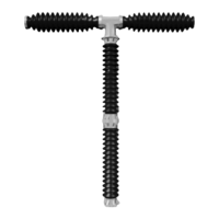
Figure 5-1. Operating mechanism.
5.2 Assembly of busbars or overhead lines
WARNING
Work must not be carried out on a pressurised circuit-breaker.
High-voltage conductors consisting of aluminium busbars or aluminium connectors
for overhead lines can, after being treated with contact paste, be directly connected
to the breaking unit’s terminal flags, which are also made of aluminium.
However, if copper busbars or copper connectors are used for the overhead lines,
grease should be used and a bimetallic washer fitted in the joint. Bimetallic washers
can be supplied by ABB on request.
1
B10015
 Loading...