15
cs
I
∆
n
I
I
%
[]
∆
1
∆
n
I
I
%
[]
∆
2
∆
k
∆
2
t
∆
1
s
[
]
t
rec
min
[
]
<
s
[
]
n
<
I
I
/
t
a
min
[ ]
b
I
I
%
[ ]
a
I
I
/
b
k
t
n
>
>
>
>
n
I
%
[]
∆
Register Recorded information
0 Display of blocking signals and other external control signals.
The right-most digit indicates the state of the blocking inputs of the unit. The
following states may be indicated:
0 = no blocking signal
1 = the control or block signal BS1 is active
2 = the control or block signal BS2 is active
3 = the control or block signals BS1 and BS2 are active
4 = the control or block signal RRES is active
5 = the control or block signals RRES and BS1 are active
6 = the control or block signals RRES and BS2 are active
7 = the control or block signals RRES, BS1 and BS2 are active
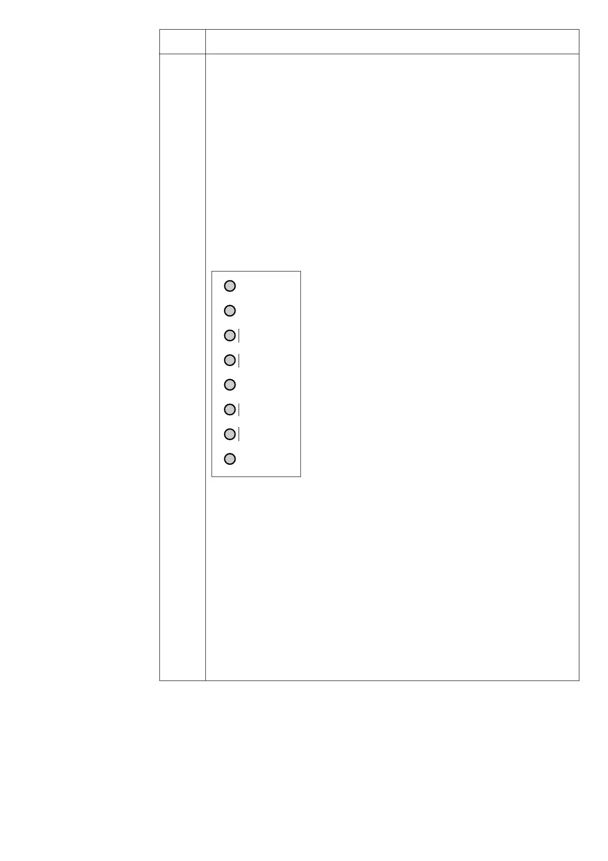
From this register "0" it is possible to move on to the TEST mode, where the start-
ing and tripping signals of the module are activated one by one in the following
order and indicated by the flashing setting indication LED:
Start from I
b
>
Trip from I
b
>
Trip from I
a
>
Trip from I<
Reconnection inhibit
Trip from ∆I
1
>
Start from ∆I
2
>
Trip from ∆I
2
>
The led positions adjacent to SGF, SGB and SGR are not tied to any test function.
For further details see the description "General characteristics of D-type SPC relay
units".
A The address code of the measuring relay module, required by the serial communica-
tion system. // The selection of the data transfer rate of the serial communication.
// The bus traffic monitor indicating the operating state of the serial communica-
tion system. If the module is connected to a system including a control data com-
municator and if the communication system is operating, the counter reading of the
bus traffic monitor will be zero. Otherwise the numbers 0...255 are continuously
rolling in the display. // Password required for the remote control of the settings.The
password must always be entered via the serial communication before setting can be
remotely altered.
The registers 1...9 are set to zero by pressing the
push-buttons RESET and PROGRAM simul-
taneously. The registers are also cleared if the
auxiliary power supply module is interrupted.
The address code of the plug-in module, the
data transfer rate of the serial communication
and the password are not erased by a voltage
failure. Instructions for setting the address and
the data transfer rate are given in the manual
"General characteristics of D type SPC relay
units".

 Loading...


