ABB Transformer Protection Unit 2000R
4-7
Relay Design and Specifications
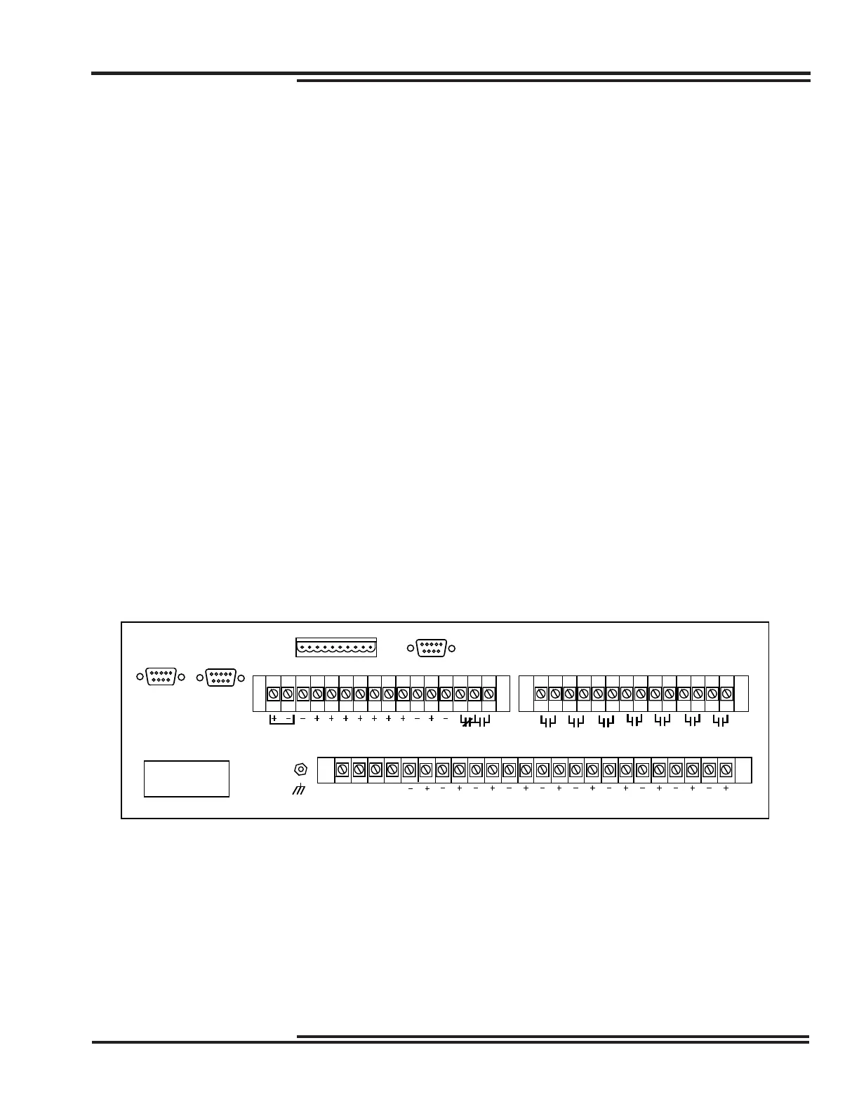
Rear Terminal Block Connections
Apply only rated control voltage marked on the front panel of the unit to the positive terminal and the negative
terminal. Wire the ground stud on the rear of the case to the equipment ground bus with at least #10 gauge wire.
Figure 4-3 shows the rear terminal block layout and numbers.
Tables 11-1 and 11-2 lists the minimum required connections for a functioning system. Optional connections are
shown on the bottom of the table. Jumper #6 is used to set the TRIP Output Contact to Normally Open or Normally
Closed.
Figure 4-3. Rear Terminal Block
SENSOR 7
CONT.INST. BOOK
SERIAL NO.
CATALOG NO.
TYPE
GRD
PHASE
FREQ.
COM 1 COM 2
VNVCVBVA
SENSOR 8
IN
1
VDC
COM-
MON
IN
2
IN
3
IN
4
IN
5
57
4
AUX.
PORTS
123
56
55
5
58
6
60
59 61
7
62
8
64
63
IN
6
IN
7
IN
8
31 32 33 34
39 40 41
SELF-CHECK
ALARM
11910 12131415
COM 3
ISOLATED
16
SENSOR 3
SENSOR 5SENSOR 6
SENSOR 4
SENSOR 1SENSOR 2
= OPTIONAL CONTACT CONFIGURATION
OUT 5
42 43 44 45
OUT 6
46 47 48 49
OUT 4 OUT 3
17 18 19
*
SELECTABLE N.O. OR N.C.
222120 23 24
5350 51 52
OUT 2
*
OUT 1
*
54
*
TRIP
2925 26 27 28 30
GND
SENSOR 9
35 36 37 38
SENSOR 10