ABB Transformer Protection Unit 2000R
4-9
Relay Design and Specifications
Built-In Testing
The TPU-2000R continuously checks itself for proper functioning.
Self-Test Status
The TPU-2000R provides continuous self-testing of its power supply voltages, memory elements, digital signal processor
and its program execution. In the event of a system failure, the protective functions are disabled and the Self-Check
Alarm contacts are actuated. Except for a “processor stalled” condition, review the PASS/FAIL status of these self-test
elements by using the man-machine interface (MMI). Normal status is indicated by a green TPU STATUS light (LED)
and system failure is indicated by a red TPU STATUS light (or by the green TPU STATUS light not being lit in the case
of a loss of control power). If the green light is flashing, refer to the Operations Menu in Section 9.
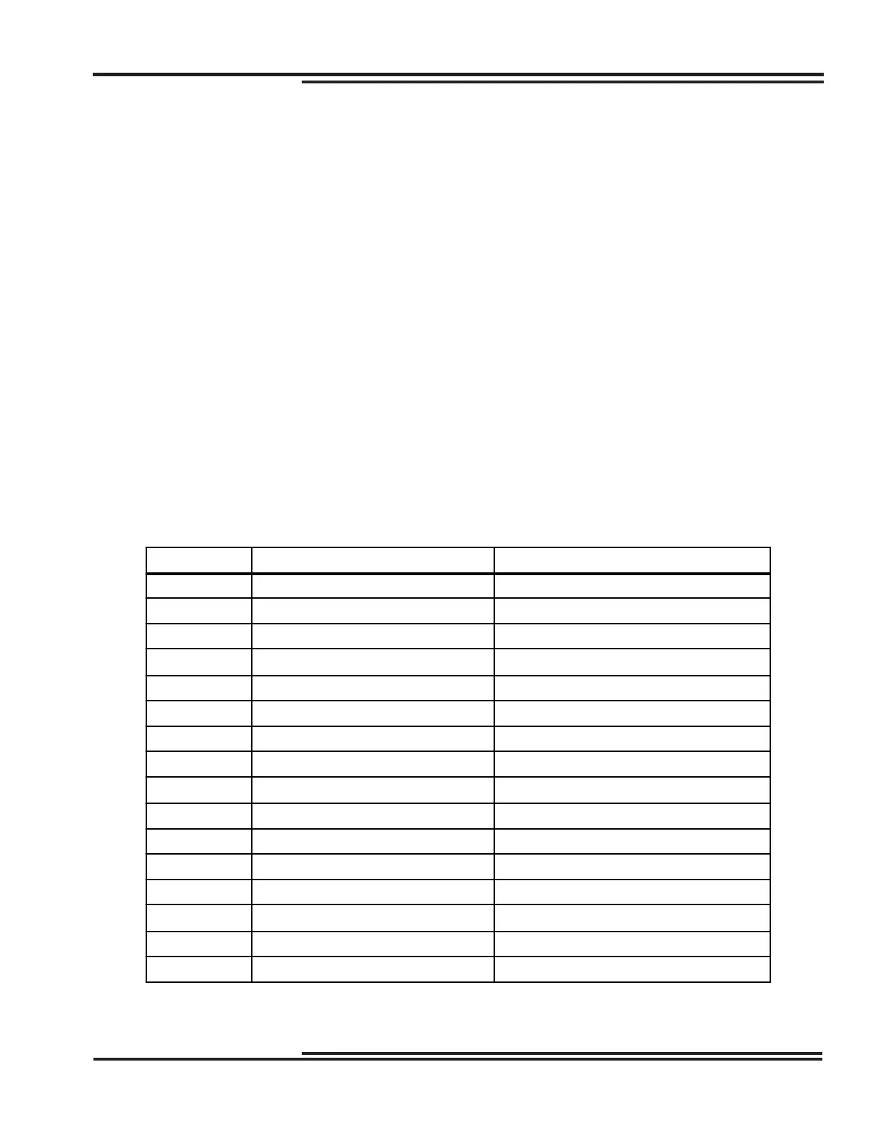
Self-Test Failures are recorded as a number in the Operations Record. The binary bit pattern of this number indicates
the Self-Test Failure or Editor Access Status involved. The 1’s in the bit pattern indicate where a failure has occurred.
Count from the right of the bit pattern (starting with zero) to the position where a “1” occurs. Compare that bit position
with Table 4-1 to reveal the failure. See the following examples for further explanation.
If the self-test fails, the TPU-2000R is no longer providing protection. Replace the unit as soon as possible.
Table 4-1. Operations Record Value Information
Bit Position Self-Test Failure Editor Access Status
0 CPU RAM INTERRUPT LOGGING
1 CPU EPROM REMOTE EDIT DISABLE = 1
2 CPU NVRAM LOCAL EDIT DISABLED = 1
3 CPU EEPROM FRONT MMI EDIT ACTIVE
4 NOT USED FRONT COMM PORT EDIT ACTIVE
5 NOT USED REAR COMM PORT EDIT ACTIVE
6 NOT USED REAR AUX COMM PORT EDIT ACTIVE
7 NOT USED REAL TIME CLOCK EDITED
8 DSP ROM PROGRAMMABLE I/O EDITED
9 DSP INTERNAL RAM PRIMARY SET EDITED
10 DSP EXTERNAL RAM ALTERNATE1 SETTINGS EDITED
11 DSP ANALOG/DIGITAL CONVETER ALTERNATE2 SETTINGS EDITED
12 DSP +/-5 V POWER SUPPLY CONFIGURATION SETTINGS EDITED
13 DSP +/-15 V POWER SUPPLY COUNTER SETTINGS EDITED
14 DSP STALL or +5 V POWER SUPPLY ALARM SETTINGS EDITED
15 DSP TO CPU COMMUNICATIONS COMMUNICATIONS SETTINGS EDITED
#
#
 Loading...