- 64 -
000510AG
For long distance connections, the connection on the terminal connector
is preferable using a shielded twisted pair cable with characteristic im-
pedance of Z0=120 Ohm like the one shown on the following table:
Signal Symbol
-T/R
+T/R
RTN
-T/R
+T/R
RTN
SHIELD
SHIELD
Positive data +T/R
Negative data -T/R
Reference RTN
Screen
Shield continuity must be provided along the communication line and must be grounded at a
single point.
When the inverter has been connected to the monitoring system, the com-
munication line terminating resistor has to be activated by setting the des-
ignated RS485 line termination jumper
15
to ON.
15
15
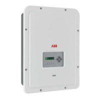
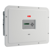
UNO-2.0/3.0-TL-OUTD-S
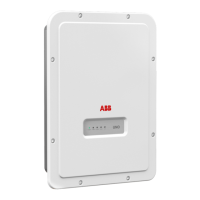
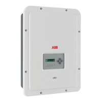
UNO-3.6/4.2-TL-OUTD-S
The inverter must not have “Auto” as an address. An address can be
freely chosen between 2 and 63.
The setting of the address on the inverter is done through the display and
the keyboard (see the specic chapter).
Each inverter is supplied with a preset RS485 address of two (2) and with
the jumper for setting the termination resistance
15
in the OFF position.
ON OFF
TERM.
J25
120Ω
TERM.
120Ω
ON OFF
J26
OFF
ON
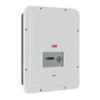
UNO-2.0/3.0-TL-OUTD-S
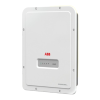
UNO-3.6/4.2-TL-OUTD-S
Скачано с сайта интернет магазина https://axiomplus.com.ua/
 Loading...
