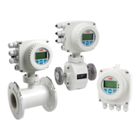
Electromagnetic Flowmeter
WaterMaster 3 Mechanical Installation
IM/WM Issue 7 13
Fig. 3.23 DN 700 to 2200 Full Bore
Meter Size Dimensions in mm (in)
DN NPS/NB A B
350 14 535 (21.1) 550 (21.7)**
400 16 600 (23.6) 600 (23.6)**
450 18 640 (25.2) 698 (27.5)**
500 20 715 (28.1) 768 (30.2)**
600 24 840 (33.1) 918 (36.1)**
700 27/28* 927 (36.5) 700 (27.6)***
750 30 985 (38.8) 762 (30)***
800 32 1060 (41.7) 800 (31.5)***
900 36 1170 (46.1) 900 (35.4)***
1000 39/40* 1290 (50.8) 1000 (39.4)***
1100 42 1405 (55.3) 1067 (42)***
1200 48 1511 (59.5) 1200 (47.2)***
1400 54 1745 (68.7) 1400 (55.1)***
1500 60 1855 (73.0) 1524 (59)***
1600 66 2032 (80.0) 1600 (63)***
1800 72 2197 (86.5) 2250 (88.6)***
2000 78 2362 (93.0) 2500 (98.4)***
2200 84 2534 (100.0) 2750 (110)***
* Size is dependent on flange specification
Typical tolerances: **+0/–6 mm (0.24 in): ***+0/–10 mm (0.40 in)
Items **/*** DN700 up +0/–25 mm (1.0 in) if using WN flanges
Table 3.3 DN 350 to 2200 Full Bore
A
B
Max.Max.

 Loading...