2106001MNAA | XSERIES G5 START UP GUIDE | 19
3. One (1) manifold (3-valve or 5-valve manifold determined by
technician.)
To install the input lines and manifold (XFC):
1. Install the manifold on the XFC IMV using the manufacturer's supplied
instructions.
2. Locate the tap valves on the meter run orifice and the corresponding
high and low inputs on the installed manifold.
3. Measure, cut, and bend the tubing to ease installation of the fittings
into the orifice tap valves and the manifold.
4. Install the nut and ferrule onto the tubing end.
NOTICE – Equipment Damage.
To avoid damage to the stainless
steel tubing, fittings, and valves, always use a backup wrench
to stabilize and eliminate tension on both sides of the
connection when tightening. Damaged connections may
introduce leaks into the system resulting in inaccurate
measurement
5. Insert the ferrule into the fitting and slide the nut onto the ferrule;
engage the nut threads and tighten.
6. Repeat step 5 for each tubing connection point.
Manifold and tubing connections must be leak-tested before power
application. Connection leaks between the tap valves, the orifice, the
manifold, and the XIMV can introduce measurement and calibration errors.
Materials:
Liquid leak detector
Pressure calibration device
DANGER – Serious damage to health / risk to life. Manifold
and tubing connection leaks could create a build-up of
explosive gases. Do not apply power before the tubing and
connections are leak-free, and explosive gases have
dissipated.
To leak-test the manifold and tap valve connections:
1. Open the equalizer valves
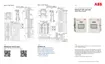
Figure 2-3: XFC with XIMV and 5-valve
manifold (items 1 and 3) and close the Manifold vent valve (item 2).
 Loading...