38 | XSERIES G5 START UP GUIDE | 2106001MNAA
Digital input and output (DI/DO) pinouts
IMPORTANT NOTE: Digital inputs may be used as Pulse Inputs.
The XFC has 2 onboard digital outputs and 2 onboard digital inputs.
Figure
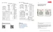
5-3 shows the Digital I/O terminals on the XFC and the input mode
switches. The input mode switches support standard pulse inputs (STD) or
pulse inputs from Coriolis (IEC). Remember to set the switch to the correct
position based on the type of pulse input signal expected. Use S3 for DI/PI
1 or S4 for DI/PI 2.
Listed below are the DIs and DOs for the XFC and the XRC.
Figure 5-3: XFC DI/PI/DO terminals and input mode switches
Table 5-3: XFC DI/PI/DO pinouts
 Loading...