å
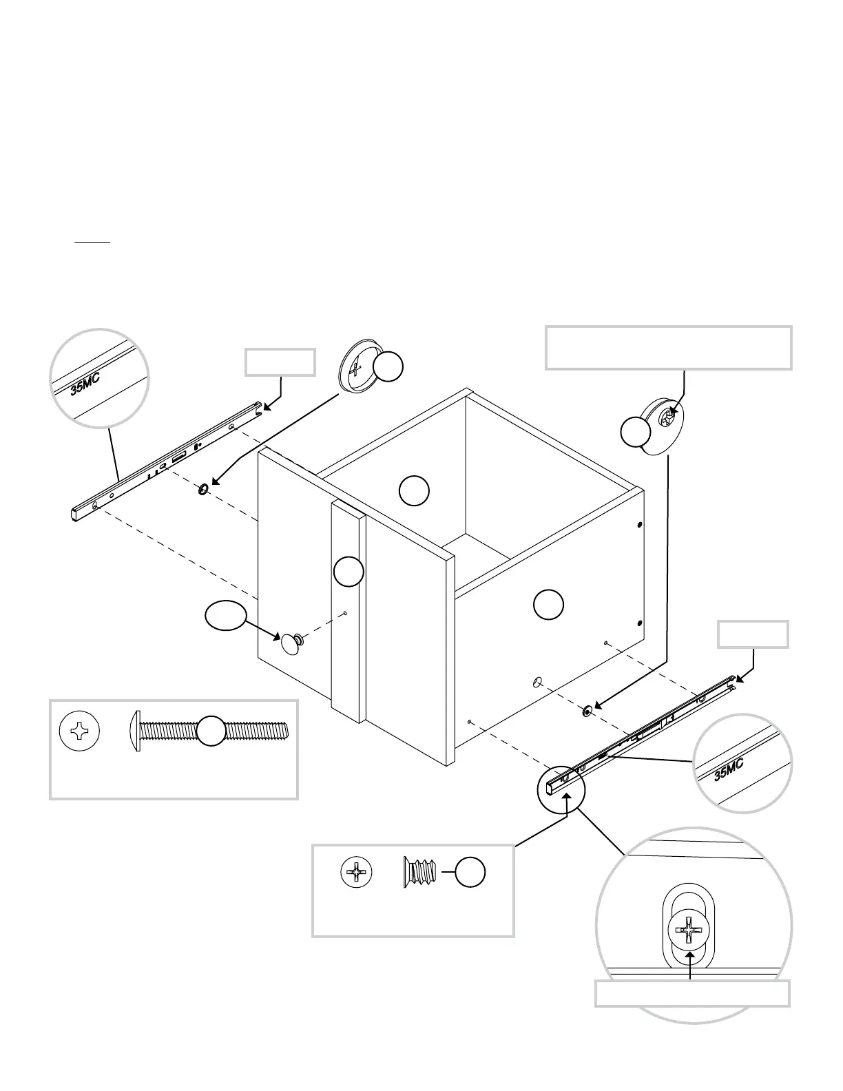
Insert a SLIDE CAM (10A) into each DRAWER SIDE (D14 and D15).
å
Fasten the EXTENSION SLIDES (35MC) to the DRAWER SIDES (D14 and D15). Use four
GOLD 5/16" FLAT HEAD SCREWS (3S) throuh holes #1 and #3.
å
NOTE: The screw head in the CAM must be visible throuh the slotted hole in the SLIDE.
å
Fasten the KNOB (187K) to the DRAWER FRONT MOLDING (K). Use one SILVER 1-1/2"
MACHINE SCREW (95S).
Step 30
Pae 35
Open end
Screw head - turn CAM to line up holes in
the SLIDES with holes in DRAWER SIDES
1
2
3
10A
10A
1
2
3
Open end
GOLD 5/16" FLAT HEAD SCREW
(4 used for the SLIDES)
3S
Drawer Slide
Center the screw in the oval hole.
D15
D14
K
SILVER 1-1/2" MACHINE SCREW
(1 used for the KNOB)
95S
187K
 Loading...