This document outlines a series of training exercises for the ABI System 8 Board Fault Locator (BFL) and BoardMaster modules, focusing on various aspects of circuit testing and fault diagnosis. The training board, pictured in the document, is designed to demonstrate the full functionality of these modules by presenting examples of both circuit and fault conditions. It includes simple circuits for training in basic electronic principles and is structured to provide optimum coverage for each aspect of the equipment. Circuit and fault conditions can be applied by activating a switch connected to a PIC, which then energizes relays to alter the circuit by switching in components.
The ABI System 8 is a comprehensive test and measurement equipment designed for contract electronics manufacturing, offering tools for identifying, diagnosing, and locating faults on printed circuit boards (PCBs). Its core function is to facilitate efficient and accurate fault-finding, which is crucial in electronics manufacturing and repair.
Function Description
The ABI System 8 provides a range of testing capabilities, including:
- IC Tester: This module performs various tests on integrated circuits (ICs), such as Truth Table tests, Connections tests, Voltage tests, and V-I (Voltage-Current) tests. It can identify ICs, detect open circuits, shorts, and other anomalies.
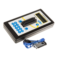
- Board Fault Locator (BFL): The BFL is a key component for power supply and fault location. It provides a 5V @ 5A supply for IC tests and is integral to the overall PCB power management during testing. It also supports advanced fault location techniques like Short Location.
- Training Board: A dedicated PCB designed with various ICs (e.g., 74LS00, 74LS161, 74LS244, EPROM) and configurable fault conditions to simulate real-world scenarios for training purposes.
- TestFlow: A feature that allows users to create and execute sequences of tests, enabling automated and repeatable fault diagnosis routines.
- Live Comparison: This feature allows for direct comparison between a known good PCB and a suspect PCB, highlighting differences in test results.
Important Technical Specifications
While specific detailed technical specifications for each component are not exhaustively listed in the provided excerpts, several key operational parameters and features are mentioned:
- Power Supply: The BFL provides a 5V @ 5A supply for IC tests. This is a critical specification for powering the device under test (DUT) during various diagnostic procedures.
- Voltage Test Thresholds: The system uses configurable logic level thresholds (e.g., 2.4V for TTL, 4.0V for 74C type) for voltage tests, which are crucial for accurate logic state determination.
- V-I Test Ranges: The Digital V-I tests can be configured with different voltage ranges (e.g., +/- 5V, +/- 10V) to provide detailed trace analysis around diode junctions.
- Short Detection: The system can detect shorts with resistance as low as 1.5 Ohms to GND or 5V, indicating a sensitive short detection capability.
- Memory Testing: The system supports testing of EPROMs (e.g., 256k by 8) and includes checksum verification for memory integrity.
- Channels: The Live Comparison feature requires two BFL modules, supporting 128 channels, implying a high-density testing capability.
- Clock Signals: The system can generate and analyze clock signals up to 4MHz for testing sequential devices.
Usage Features
The ABI System 8 is designed for ease of use and comprehensive fault diagnosis:
- Intuitive User Interface: The software includes a graphical user interface with windows for Test Results Analysis, IC diagrams, and SETUP configurations, making it user-friendly.
- Clip Orientation: The system can automatically orientate the IC clip position, especially for V-I tests, simplifying setup and reducing errors.
- Device Selection: Devices can be selected by typing the number directly or by filtering through groups, with support for prefixes and suffixes.
- Test Types: A wide array of test types are available, including Truth Table, Connections, Voltage, Thermal, V-I, Memory, and Signal Detection, allowing for thorough PCB analysis.
- Fault Simulation: The training board allows for the introduction of various fault conditions (e.g., open circuits, shorts, mid-level inputs, conflicts, bus disable) to provide hands-on experience in fault diagnosis.
- Ground Clip: The ground clip is used to reduce backdriving noise caused by current surges, especially when testing sequential devices, ensuring more accurate test results.
- Bus Disable Output (BDO): This feature allows disabling outputs on the bus to isolate devices and prevent conflicts, which is critical for testing bus-structured circuits.
- Short Locator: An instrument with audible indication helps pinpoint the exact location of shorts on the PCB, making physical fault finding more efficient.
- Loop Mode: The voltage test can be run in a Loop mode to observe active signals and changing logic states, which is useful for dynamic circuit analysis.
- TestFlow and Live Comparison: These features enable automated, repeatable testing and direct comparison with known good boards, streamlining the diagnostic process.
- Automatic Circuit Compensation: The software includes features to compensate for variations in track width, height, and length, improving the accuracy of resistance measurements during short location.
Maintenance Features
While explicit maintenance features are not detailed, the design implies several aspects that contribute to the maintainability and reliability of the system:
- Modular Design: The system's modular nature, with components like the BFL and BoardMaster, suggests that individual modules can be serviced or replaced if necessary.
- Software Updates: The system's reliance on software for test execution and analysis implies that updates can be provided to enhance functionality, improve accuracy, and address bugs.
- Training and Documentation: The comprehensive training exercises and detailed descriptions within the manual serve as a valuable resource for users to understand and troubleshoot the system effectively.
- Fault Isolation: The various diagnostic tools (e.g., IC Tester, Short Locator) are designed to isolate faults to specific components or tracks, which aids in targeted repair and maintenance.
- External Supply Support: The ability to use an external power supply for higher current UUTs (Units Under Test) suggests flexibility and protection for the internal BFL supply.
- Pre-Search Checks: The IC Identifier performs pre-search checks to ensure good IC connections and proper activity, reducing false positives and improving diagnostic efficiency.
In summary, the ABI System 8 is a robust and versatile test and measurement solution for electronics manufacturing, offering a comprehensive suite of tools for IC testing, fault location, and PCB diagnosis, supported by a user-friendly interface and extensive training resources.